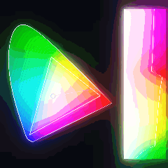
PL. 129 · COLOUR / CHROMATICITY / GAMUT BOUNDARY
sRGB Gamut
the CIE 1931 system: T. Smith & J. Guild, 1931 · sRGB: M. Anderson, R. Motta, S. Chandrasekar & M. Stokes, 1996 · the colour matching fit: Wyman, Sloan & Shirley, 2013
OPEN THE LIVE PLATE ▸DEFINITION
x = X/(X+Y+Z),   y = Y/(X+Y+Z)
locus: (x(λ), y(λ)) from the analytic x̄ ȳ z̄ fit,  λ ∈ [440, 640] nm
gamut: the triangle on R (0.640, 0.330), G (0.300, 0.600), B (0.150, 0.060)
outside it: the nearest point of that triangle, in the xy plane
NOTES
Two claims in one picture. The horseshoe is every chromaticity the eye can distinguish, arranged so that mixing two lights lands the result on the straight line between them — that property is the reason this diagram is worth drawing rather than merely worth looking at. Its curved edge is the pure spectrum, one point per wavelength; the chord that closes it along the bottom is the line of purples, colours that have no wavelength at all and exist only as mixtures of the two ends. The triangle is what a screen can do. Three primaries means three corners, and mixing can never leave the triangle they span, which is the same convexity turned against the reader. So everything inside the horseshoe and outside the triangle is a colour the eye can see and this screen cannot make, and by area that is about two thirds of the picture. Which raises the question of what is drawn there, and the answer is: the nearest colour the screen does have. Every point outside the triangle is painted as the closest point on it, so a whole two-dimensional region is folded onto a one-dimensional edge, and out there the colours stop changing as you move away — frozen, in fans, one fan per edge and one per corner, with rings marking how far each point had to be moved to become representable. That fold is not a shortcut taken here. It is what every printed reproduction of this diagram has always done, usually in silence, and it is why no reproduction of it can be trusted about its own outer region. The panel on the right is the same field in polar form about the white point, angle running down and distance running across, so the white point is its left edge and the spectral boundary its right. The seam running down it is where the triangle ends, and its position reads off directly as the fraction of that hue the screen can reach: about 92 per cent toward a dominant wavelength near 611 nm, and about 22 per cent near 510 nm, where the eye is furthest ahead. That window travels, which is the drift. Two things the diagram is deliberately not saying. The triangle is the union over every brightness: hold the luminance fixed and the reachable set is a smaller polygon inside it, six-sided across most of the range and collapsing to a point at black and at white, so the triangle flatters the screen rather than the eye. And distance in this plane is not perceived distance, which MacAdam measured in 1942 — so the nearest point in xy is a defensible choice and not the only one, and the dial that swings the clip toward the white point instead shows how much of the picture that choice decides.
PROVENANCE
- Origin
- T. Smith and J. Guild, "The C.I.E. colorimetric standards and their use", Transactions of the Optical Society 33(3), 1931, 73–134 — the paper that sets out the standard trichromatic system this diagram is, including the transformation to the X, Y, Z primaries and the x, y chromaticity plane the plate draws. Verified against Crossref on title, both authors, year, venue, volume, issue and pages before it was cited here. The colour matching experiments underneath it are W. D. Wright, "A re-determination of the trichromatic coefficients of the spectral colours", Transactions of the Optical Society 30(4), 1929, 141–164 (doi:10.1088/1475-4878/30/4/301) and J. Guild, "The colorimetric properties of the spectrum", Philosophical Transactions of the Royal Society A 230, 1931, 149–187 (doi:10.1098/rsta.1932.0005) — both verified the same way, and both are the data rather than the system, which is why the system is the citation above.
- Standing
- Public domain. A coordinate system published in 1931 and a colour space published as an open proposal in 1996, implemented here from the geometry they define — a projective normalisation, a convex hull and a triangle. No patent ever applied to any of it. Nothing is taken from any colour science or rendering codebase.
- The gamut, and where its numbers come from
- M. Anderson, R. Motta, S. Chandrasekar and M. Stokes, "Proposal for a Standard Default Color Space for the Internet—sRGB", Color and Imaging Conference 4, 1996, 238–245 (doi:10.2352/cic.1996.4.1.art00061) — verified on Crossref on title, all four authors in that order, year, venue, volume and pages. Note the author order: this work is very often cited with Stokes first, and Crossref does not agree. The space was standardised afterwards as IEC 61966-2-1, which is a standards document rather than a paper and carries no DOI, so it is named and not linked. The three primary chromaticities the plate draws are that standard, which takes them from ITU-R BT.709.
- The colour matching functions, and why the tables are absent
- Turning a wavelength into a chromaticity needs the CIE 1931 standard observer, whose tabulated x̄ ȳ z̄ values are asserted-copyright and are therefore not in this tree and never will be. What is here instead is the published analytic fit: C. Wyman, P.-P. Sloan and P. Shirley, "Simple Analytic Approximations to the CIE XYZ Color Matching Functions", Journal of Computer Graphics Techniques 2(2), 2013, 1–11 (jcgt.org/published/0002/02/01/) — seven piecewise-continuous Gaussian lobes, three for x̄ and two each for ȳ and z̄, evaluated here from the amplitudes, centres and reciprocal widths of Equation 4 and Table 1. Those coefficients are the content the paper exists to publish, offered so that people implement them instead of copying tables; using them is attribution, given here in full, and not a licence. No code was taken: the paper ships a C listing and a supplemental repository and neither was read into this implementation. Blackbody, dispersion and metamer carry the same fit, written out separately in each — four copies of seven lines rather than one shared helper, because a specimen has to be readable on its own in the drawer.
- Used past what it was fitted to, and cut back to where it holds
- Blackbody states the rule this plate has to break: the paper fits absolute error in x̄, ȳ and z̄, so a ratio between them is a quantity it never promised. A chromaticity is exactly that ratio, and out in the tails, where all three curves are near zero, it is a ratio of two small errors. Measured, that is not a caution but a wall. At 700 nm the whole observer sums to 0.0099 and the fit puts the locus at (0.566, 0.434) against the published (0.7347, 0.2653) — 0.2387 away, most of the way across the diagram. So the band is cut, and cut by a test the plate can run on itself rather than by a threshold chosen to look reasonable: a locus turns consistently one way and winds once about any interior point, and a curve with a cusp in it is provably not one. Probed at 0.25 nm, the polar angle of this fit about D65 is strictly monotone on 439.5 to 644.0 nm and nowhere wider; the plate draws 440 to 640, inside that run with a margin. Below 440 the curve doubles back near 431 and again near 397, and above 644 it turns and climbs toward (0.04, 0.96), which is why an uncut band puts the sRGB red and blue primaries outside the visible region altogether — a screen primary the eye cannot see, which is nonsense, and is the failure this cut exists to prevent.
- What the cut costs, measured
- Almost nothing, because the true locus converges at both ends while the fit diverges. The drawn red corner is (0.7215, 0.2785) and sits 0.019 from the published chromaticity of the CIE R primary, which is monochromatic 700 nm light; the drawn blue corner is (0.1698, 0.0090) and sits 0.005 from the published chromaticity of the B primary at 435.8 nm. The enclosed area has plateaued too — 0.3243 over 430 to 650, 0.3240 over 440 to 640, 0.3234 over 425 to 655 — so widening the band adds cusps rather than area. The line of purples is therefore a little shorter and a little higher here than in a tabulated diagram, and that is the whole visible price.
- Checked, not just plotted
- Four figures, none of which the implementation could have arranged. First, the observer: the CIE R, G and B primaries are monochromatic lights at 700.0, 546.1 and 435.8 nm, and their chromaticities are published single numbers rather than a table. The fit lands 0.0027 from the published 546.1 nm point and 0.0016 from the 435.8 nm point, which is the accuracy the band is drawn on, and 0.2387 from the 700 nm point, which is the reason the band stops short of it. Second, the triangle: the plate carries the three published primary chromaticities as geometry and the standards own XYZ-to-linear-sRGB matrix as arithmetic, and never reconciles them. Walked along all three edges at a thousand steps each, the channel that should vanish there does so to 4.07e-8 of the largest — the two independent statements of what sRGB is name the same triangle to four parts in a hundred million. Third, the white point: the same matrix applied to the published D65 chromaticity returns (0.9998, 1.0000, 1.0002), neutral to four decimal places, so the diagram is centred on its own white rather than near it. Fourth, the covered area: 34.58 per cent of the locus at the published sample count, against 34.49 at 512 samples — the figure the eye reads off this plate is the converged one to within a tenth of a point. That number is over this locus, which is the analytic observers own curve and not the tabulated one, and it would move if the tables were used.
- The search, and why both paths agree
- The boundary is found by angle, not by testing every edge. The locus polygon is star-shaped about D65 — measured, it winds exactly once at every sample count in range, with the largest angular step 109.33 degrees at 12 samples, so a ray meets it exactly once — which turns the boundary lookup into a binary search over the vertex index. The JS path caches the polygon and its angular ladder once per sample count and searches the cache; the shader has nowhere to cache and evaluates the fit at the probe indices instead — one for the reference bearing, six probes at the published count, two for the segment finally found, so nine evaluations a fragment against sixty-four for a sweep of the polygon, and ten at the sample ceiling. Same object, same search, same answer: checked against an exhaustive edge sweep at twenty thousand bearings and four sample counts, the bisection disagrees zero times. Emulated in float32 across twenty thousand query angles it resolves to a different segment zero times as well, and the smallest angular step it must separate is 0.1364 degrees at 96 samples, four orders of magnitude above what a 32-bit float can distinguish there. The two paths were then compared as pictures rather than as arguments: the JS shade callback against a statement-for-statement transliteration of the shader, at eight settings across three frame sizes, 745,200 channels, and not one of them differs by a single level.
- Constants
- samples is the quadrature, the polygon and the search bound, locked from regenerate for the reasons in taxonomy.js; the covered-area figure moves from 36.11 per cent at 12 to 34.53 at 96, so the dial is fineness rather than shape. clip picks the target an unrepresentable colour is moved to: 0 is the nearest point of the triangle in the xy plane, which is what the plate claims by default, and 1 is the point where the ray from the white point leaves the triangle, which is what keeps the hue angle fixed and is standard practice in gamut mapping. Values between are the point that far along the segment joining the two, which is inside the triangle and therefore still representable, so the dial has no dead position and no illegal one — but the middle is neither published strategy and the plate says so rather than implying a family. contour is the spacing of the clip-distance rings in thousandths of a chromaticity unit, and its floor is a measurement of the weaker of the two paths rather than a round number. The shader draws at the backing resolution, where the finest setting is a 12.2 pixel period at 900 across; the JS path shades through pixels() at 200 cells, where the same setting is 2.71 cells. Twelve was the first floor tried and it measures 2.03 cells, which is the sampling limit exactly — the rings stop being rings there and become a texture — so the floor is 16. fade is the falloff of the clipped region with clip distance, in inverse chromaticity units; the furthest any point is moved is 0.3163 under the nearest-point target and 0.4165 under the radial one, so the ceiling of 6 dims the far corner to 0.15 while 0 leaves the fans flat, and both are legible. Liveness: all 400 tuples drawn uniformly from the whole declared box, and all 240 drawn the way regenerate actually jitters, clear the blank threshold by a wide margin — the lowest luminance range anywhere in either sweep is 248.3 of 255 against a floor of 14, because this plate is a filled field of colour and dimness is not among its failure modes. Travelled alone, every slider moves the picture at every step: the smallest single step is samples between its two highest positions, at 0.05 levels of mean absolute change, which is the quadrature converging rather than a dial going dead.
- Source
- doi:10.1088/1475-4878/33/3/301
TOUCHDESIGNER · GLSL
The same shader this plate runs, reframed for a GLSL TOP. Pasted bare it renders the published constants as a still frame; wire absTime.seconds into u_t on the Vectors page to animate it.
// FORMA — PL. 129 · SRGB GAMUT — the CIE 1931 system: T. Smith & J. Guild, 1931 · sRGB: M. Anderson, R. Motta, S. Chandrasekar & M. Stokes, 1996 · the colour matching fit: Wyman, Sloan & Shirley, 2013
//   x = X/(X+Y+Z),   y = Y/(X+Y+Z)
//   locus: (x(λ), y(λ)) from the analytic x̄ ȳ z̄ fit,  λ ∈ [440, 640] nm
//   gamut: the triangle on R (0.640, 0.330), G (0.300, 0.600), B (0.150, 0.060)
//   outside it: the nearest point of that triangle, in the xy plane
// TouchDesigner port — paste into a GLSL TOP's pixel shader. Set the
// resolution on the TOP's Common page. As pasted it renders the published
// constants as a still frame; to animate, add a uniform named u_t on the
// GLSL TOP's Vectors 1 page with the expression absTime.seconds.
// Constants are consts — edit to tweak; comments give the measured range.
// Written from the published mathematics, not adapted from any code.

#define u_res (uTDOutputInfo.res.zw)
uniform float u_t;               // absTime.seconds on the Vectors page; unset = still

const float u_phase = 0.8268;    // this plate's own grid phase, 0..1
// FORMA's COLOUR accent as cosine-gradient coefficients
const vec3 u_pal_a = vec3(0.46, 0.2002, 0.3896);
const vec3 u_pal_b = vec3(0.5, 0.2176, 0.4235);
const vec3 u_pal_c = vec3(1, 1, 1);
const vec3 u_pal_d = vec3(0, 0.05, 0.1);

const float p_samples = 64.0;        // locus wavelength samples · live 12 .. 96
const float p_clip    = 0.0;         // clip target — 0 nearest, 1 toward white · live 0 .. 1
const float p_contour = 20.0;        // clip contour spacing (thousandths) · live 16 .. 60
const float p_fade    = 2.6;         // clip falloff · live 0 .. 6

/* The order's ramp — the same cosine formulation the JS kit uses, so a
   plate keeps its classification colour in either language. */
vec3 ramp(float t){
  return clamp(u_pal_a + u_pal_b * cos(6.28318530718 * (u_pal_c * t + u_pal_d)), 0.0, 1.0);
}

/* Sawtooth and triangle on this plate's phase, mirroring the JS kit. */
float cycle(float t, float period){ return fract(t / period + u_phase); }
float pingpong(float t, float period){
  float u = cycle(t, period);
  return u < 0.5 ? u * 2.0 : 2.0 - u * 2.0;
}


/* The chromaticity plane of the CIE 1931 system, with the sRGB gamut inside
   the spectral locus. Every fragment is decided by its own chromaticity and
   nothing else, so this shader is the plate rather than a picture of it.

   The CIE tabulations are asserted-copyright and are not in this tree; what
   is here is the published analytic fit of Wyman, Sloan and Shirley (JCGT
   2(2), 2013), evaluated from the coefficients of its own Equation 4 and
   Table 1 — and used past what it was fitted to, which is why the band is
   cut where the JS path and the provenance say it is cut.

   Every numeric constant below is declared inside the function that uses it
   or returned by a zero-argument function, never at file scope. A
   composition emits two copies of a body and namespaces only the function
   declarations, so a file-scope const would be declared twice by
   gamut x gamut and fail to link. */

/* sRGB's white, from IEC 61966-2-1: the D65 chromaticity. */
vec2 gamut_white(){ return vec2(0.3127, 0.3290); }

/* The three primaries of the same standard, taken from ITU-R BT.709. These
   points are the triangle; the matrix below is the same claim written as
   arithmetic, and the two agree to four parts in a hundred million. */
vec2 gamut_tri(int i){
  return i == 0 ? vec2(0.6400, 0.3300)
       : i == 1 ? vec2(0.3000, 0.6000)
                : vec2(0.1500, 0.0600);
}

/* One piecewise-continuous Gaussian lobe: the width differs either side of
   the centre, which is how the fit follows an asymmetry a plain Gaussian
   cannot. g and d are reciprocal widths. */
float gamut_lobe(float lambda, float a, float b, float g, float d){
  float x = (lambda - b) * (lambda < b ? g : d);
  return a * exp(-0.5 * x * x);
}

/* x-bar, y-bar, z-bar of the CIE 1931 two-degree observer: three lobes, then
   two and two. The negative amplitude is the real dip in x-bar near 500 nm. */
vec3 gamut_cmf(float lambda){
  return vec3(
    gamut_lobe(lambda,  0.362, 442.0, 0.0624, 0.0374)
  + gamut_lobe(lambda,  1.056, 599.8, 0.0264, 0.0323)
  + gamut_lobe(lambda, -0.065, 501.1, 0.0490, 0.0382),
    gamut_lobe(lambda,  0.821, 568.8, 0.0213, 0.0247)
  + gamut_lobe(lambda,  0.286, 530.9, 0.0613, 0.0322),
    gamut_lobe(lambda,  1.217, 437.0, 0.0845, 0.0278)
  + gamut_lobe(lambda,  0.681, 459.0, 0.0385, 0.0725));
}

/* Vertex k of the locus polygon: the chromaticity of one wavelength, which is
   the tristimulus values over their own sum. The band is 440 to 640 nm, which
   is where this fit is a locus at all — outside it the curve has cusps and
   turns back into the diagram. Midpoint rule, so no sample sits on a band
   end. */
vec2 gamut_vertex(int k, float fn){
  const float LO = 440.0, HI = 640.0;
  vec3 c = gamut_cmf(LO + (float(k) + 0.5) * (HI - LO) / fn);
  return c.xy / (c.x + c.y + c.z);
}

/* Where a ray leaving the white point crosses a segment. One determinant
   gives both parameters: x is the distance wanted, y only says whether the
   crossing lies on the segment. */
vec2 gamut_cross(vec2 dir, vec2 a, vec2 b){
  vec2 e = b - a;
  float den = dir.x * e.y - dir.y * e.x;
  if (abs(den) < 1e-14) return vec2(-1.0);
  vec2 f = a - gamut_white();
  return vec2(f.x * e.y - f.y * e.x, f.x * dir.y - f.y * dir.x) / den;
}

/* The angular position of a vertex, measured round from vertex zero. The
   polygon winds exactly once about D65 at every sample count in range, so
   this is strictly increasing in k and the boundary is a binary search. */
float gamut_arc(int k, float fn, float th0){
  const float TAU = 6.28318530718;
  vec2 q = gamut_vertex(k, fn) - gamut_white();
  return mod(th0 - atan(q.y, q.x), TAU);
}

/* The distance from the white point to the locus in a given direction. Seven
   probes cover every declared sample count; the search is on the index, so
   the fit is evaluated about nine times a fragment rather than once per edge.
   The last edge is the chord back to vertex zero — the line of purples — and
   the modulo makes it one more edge with no special case. The bearing arrives
   alongside the direction because the polar register already knows it and
   would otherwise pay an arc tangent to recover what it just used. */
float gamut_locusR(vec2 dir, float th, float fn){
  const float TAU = 6.28318530718;
  int n = int(fn + 0.5);
  vec2 q0 = gamut_vertex(0, fn) - gamut_white();
  float th0 = atan(q0.y, q0.x);
  float a = mod(th0 - th, TAU);
  int lo = 0, hi = n - 1;
  for (int i = 0; i < 7; i++){
    if (lo >= hi) break;
    int mid = (lo + hi + 1) / 2;
    if (gamut_arc(mid, fn, th0) <= a) lo = mid; else hi = mid - 1;
  }
  int j = (lo + 1 == n) ? 0 : lo + 1;
  return gamut_cross(dir, gamut_vertex(lo, fn), gamut_vertex(j, fn)).x;
}

/* The triangle is wound counter-clockwise, so a point is inside exactly when
   it is left of all three edges. */
float gamut_inTri(vec2 p){
  float m = 1.0;
  for (int i = 0; i < 3; i++){
    vec2 a = gamut_tri(i), b = gamut_tri(i == 2 ? 0 : i + 1);
    m = min(m, step(0.0, (b.x - a.x) * (p.y - a.y) - (b.y - a.y) * (p.x - a.x)));
  }
  return m;
}

/* The nearest point of the triangle, in the plane of the diagram: the
   perpendicular foot on each edge, clamped to the edge, nearest wins. The
   clamp is what puts a corner in play, and it is why the fans outside the
   triangle are three slabs and three wedges rather than three alone. */
vec2 gamut_near(vec2 p){
  vec2 best = vec2(0.0);
  float bd = 1e9;
  for (int i = 0; i < 3; i++){
    vec2 a = gamut_tri(i), e = gamut_tri(i == 2 ? 0 : i + 1) - a;
    vec2 q = a + e * clamp(dot(p - a, e) / dot(e, e), 0.0, 1.0);
    float d = dot(p - q, p - q);
    if (d < bd){ bd = d; best = q; }
  }
  return best;
}

/* Where the ray leaves the triangle: the other published clip target, and the
   one that keeps the hue angle fixed. */
float gamut_triR(vec2 dir){
  float best = 0.0;
  for (int i = 0; i < 3; i++){
    vec2 h = gamut_cross(dir, gamut_tri(i), gamut_tri(i == 2 ? 0 : i + 1));
    if (h.y >= 0.0 && h.y <= 1.0) best = max(best, h.x);
  }
  return best;
}

/* CIE XYZ to linear sRGB (IEC 61966-2-1 primaries at D65), then that
   standard's transfer function — a linear toe under a shifted power curve. */
vec3 gamut_rgb(vec3 c){
  return vec3( 3.2404542 * c.x - 1.5371385 * c.y - 0.4985314 * c.z,
              -0.9692660 * c.x + 1.8760108 * c.y + 0.0415560 * c.z,
               0.0556434 * c.x - 0.2040259 * c.y + 1.0572252 * c.z);
}
vec3 gamut_encode(vec3 c){
  c = clamp(c, 0.0, 1.0);
  return mix(12.92 * c, 1.055 * pow(c, vec3(1.0 / 2.4)) - 0.055, step(0.0031308, c));
}

/* A chromaticity has no brightness of its own, so the only honest way to put
   one on a screen is at the brightest triple carrying it. Feeding the matrix
   (x, y, z) rather than (x/y, 1, z/y) is the same direction scaled and the
   normalisation divides the scale straight back out, so the bottom edge of
   the diagram, where y reaches 0.009, needs no special case. */
vec3 gamut_swatch(vec2 p){
  vec3 lin = gamut_rgb(vec3(p, 1.0 - p.x - p.y));
  return gamut_encode(max(lin, 0.0) / max(max(lin.r, lin.g), max(lin.b, 1e-9)));
}

/* The colour of one chromaticity, which is the whole plate. Inside the
   triangle it is that colour. Outside it is the colour of wherever the clip
   sends it, dimmed by how far it went and ringed by contours of that
   distance. Both clip targets sit on the boundary and the triangle is convex,
   so every setting of the blend names a colour the screen really has. The
   distance to the triangle goes out through dTri, because the diagram draws
   its outline at exactly that distance read at zero and would otherwise find
   the same nearest point twice a fragment. */
vec3 gamut_field(vec2 p, vec2 dir, float blend, float sp, float fade, out float dTri){
  vec2 n0 = gamut_near(p);
  dTri = length(p - n0);
  if (gamut_inTri(p) > 0.5) return gamut_swatch(p);
  /* At blend 0 the second target is multiplied away, so it is not looked
     for — the default costs what it draws. */
  vec2 q = n0;
  if (blend > 0.0) q = mix(n0, gamut_white() + dir * gamut_triR(dir), blend);
  float d = length(p - q);
  /* Rings of constant clip distance. The lit part is a fixed fraction of the
     period rather than a fixed width, so they stay the same weight at every
     spacing and at either resolution. */
  float fr = abs(fract(d / sp) - 0.5) * 2.0;
  float rs = smoothstep(0.72, 1.0, fr);
  return gamut_swatch(q) * exp(-fade * d) * (1.0 - 0.34 * rs) + vec3(0.055 * rs);
}

/* 1 inside a mark and 0 outside it, with the transition spread over the outer
   part of its width so the edge is antialiased rather than stepped. */
float gamut_mark(float e0, float e1, float x){ return 1.0 - smoothstep(e0, e1, x); }

vec3 plate(vec2 uv){
  /* The plate in two registers, as fractions of the frame. Left: the
     chromaticity plane. Right: the same field in polar form about the white
     point, angle down and distance across, as a window that travels with the
     ray — this plate's drift. */
  const float PX0 = 0.018, PX1 = 0.700, PY0 = 0.030, PY1 = 0.970;
  const float QX0 = 0.737, QX1 = 0.988, QY0 = 0.055, QY1 = 0.945;
  const float SPAN = 3.49065850399;          // the polar window, 200 degrees
  const float VX0 = -0.035, VX1 = 0.760, VY0 = -0.035, VY1 = 0.860;
  const float TAU = 6.28318530718;
  const float LW = 0.0026, RW = 0.0020;

  float fn = max(3.0, floor(p_samples + 0.5));
  float sp = p_contour * 0.001;
  float asp = u_res.y / u_res.x;
  vec3 col = vec3(4.0, 6.0, 10.0) / 255.0;

  /* The diagram is fitted into its panel isotropically and centred. A
     chromaticity plane stretched to fill a frame would put the primaries
     somewhere they are not, which is the one thing this plate cannot do. */
  float s = min((PX1 - PX0) / (VX1 - VX0), (PY1 - PY0) * asp / (VY1 - VY0));
  vec2 pc = vec2((PX0 + PX1) * 0.5, (PY0 + PY1) * 0.5);
  vec2 vc = vec2((VX0 + VX1) * 0.5, (VY0 + VY1) * 0.5);

  /* The drift: the ray sweeps once round the white point and the register
     travels with it. cycle() carries this plate's own PHASE. */
  float rayTh = TAU * cycle(u_t, 44.0);
  /* The moving mark stays in the ramp's bright lobe — the ramp is black
     around 0.5, and this is one hairline over a field. */
  vec3 RAY = ramp(0.92);

  if (uv.x > PX0 && uv.x < PX1 && uv.y > PY0 && uv.y < PY1){
    vec2 p = vec2(vc.x + (uv.x - pc.x) / s, vc.y - (uv.y - pc.y) * asp / s);
    vec2 e = p - gamut_white();
    float rad = length(e);
    vec2 dir = rad > 1e-9 ? e / rad : vec2(1.0, 0.0);
    float rl = gamut_locusR(dir, atan(e.y, e.x), fn);

    if (rad < rl){
      float dTri;
      col = gamut_field(p, dir, p_clip, sp, p_fade, dTri);

      /* The triangle, drawn as the same nearest-point distance the clip uses,
         read at zero — so the outline cannot drift from the boundary it
         outlines. */
      col = mix(col, vec3(0.97), gamut_mark(LW * 0.5, LW, dTri * s) * 0.85);

      /* The ray. Brighter over the part of its length the screen can actually
         mix, which is the reading the register beside it gives as a seam —
         and the gamut radius is only looked for on the few fragments the
         hairline actually touches. */
      vec2 rd = vec2(cos(rayTh), sin(rayTh));
      if (rad > 0.016 && dot(e, rd) > 0.0){
        float er = gamut_mark(RW * 0.5, RW, abs(e.x * rd.y - e.y * rd.x) * s);
        if (er > 0.0)
          col = mix(col, RAY, er * (rad < gamut_triR(rd) ? 0.95 : 0.45));
      }
    }
    /* The locus itself, so the horseshoe has an edge against the ink. */
    col = mix(col, vec3(0.86, 0.88, 0.94), gamut_mark(LW * 0.5, LW, abs(rad - rl) * s));

    /* The white point everything turns about, as a dark ring rather than a
       bright one: the field is very nearly white where D65 sits, which is the
       whole point of D65, so a light mark there would be invisible. */
    col = mix(col, vec3(0.09, 0.10, 0.13),
              gamut_mark(RW * 0.6, RW * 1.5, abs(rad * s - 0.0130)));
  }
  else if (uv.x > QX0 && uv.x < QX1 && uv.y > QY0 && uv.y < QY1){
    /* The same field in polar form: angle down, distance across, so every row
       is one radius of the diagram straightened out. */
    float rowF = (uv.y - QY0) / (QY1 - QY0);
    float th = rayTh + (rowF - 0.5) * SPAN;
    vec2 dir = vec2(cos(th), sin(th));
    float rl = gamut_locusR(dir, th, fn);
    float f = (uv.x - QX0) / (QX1 - QX0);
    float dTri;
    col = gamut_field(gamut_white() + dir * (f * rl), dir, p_clip, sp, p_fade, dTri);

    /* The seam: where the triangle ends along this row, which is the fraction
       of this hue the screen can reach, read off directly. */
    col = mix(col, vec3(0.97),
              gamut_mark(RW * 0.5, RW, abs(f - gamut_triR(dir) / rl) * (QX1 - QX0)));
    /* The centre row is the ray in the panel beside it. */
    col = mix(col, RAY, gamut_mark(RW * 0.5, RW, abs(rowF - 0.5) * (QY1 - QY0) * asp) * 0.5);
  }

  return clamp(col, 0.0, 1.0);
}

out vec4 fragColor;
void main(){
  // FORMA's uv runs y-down, matching its canvas; TD's vUV runs up
  vec2 uv = vec2(vUV.s, 1.0 - vUV.t);
  fragColor = TDOutputSwizzle(vec4(plate(uv), 1.0));
}
NUKE · BLINKSCRIPT
The same shader this plate runs, transpiled to a BlinkScript kernel. Paste it into a BlinkScript node's Kernel Source and press Recompile; every constant arrives as a knob at its published value, and u_t animates with the expression frame/24. Compiled and rendered in Nuke 17.1, then compared against this plate on the page.
// FORMA — PL. 129 · SRGB GAMUT — the CIE 1931 system: T. Smith & J. Guild, 1931 · sRGB: M. Anderson, R. Motta, S. Chandrasekar & M. Stokes, 1996 · the colour matching fit: Wyman, Sloan & Shirley, 2013
//   x = X/(X+Y+Z),   y = Y/(X+Y+Z)
//   locus: (x(λ), y(λ)) from the analytic x̄ ȳ z̄ fit,  λ ∈ [440, 640] nm
//   gamut: the triangle on R (0.640, 0.330), G (0.300, 0.600), B (0.150, 0.060)
//   outside it: the nearest point of that triangle, in the xy plane
// Nuke port — a BlinkScript kernel. Paste into a BlinkScript node's Kernel
// Source and press Recompile. Every constant arrives as a knob at its published
// value (the comment gives the measured range); u_t is a knob too — animate it
// with the expression frame/24 or leave it at 0 for the still frame. Written
// from the published mathematics, not adapted from any code.
// Transpiled from the shader this plate runs on the page (GLSL ES 3.00):
// vec → float2/3/4, swizzles expanded, GLSL builtins Blink lacks written out
// as forma_ functions, float literals suffixed. Compiled and rendered in a
// real Nuke (17.1v1) and compared against this plate on the page: 34 of 34.
//
// plate() and its helpers are written to a single exit — the loop that runs
// once. That is not a style: Blink 17.1 drops a conditional early return from
// a called function while Vectorize is on, which is the node default, with no
// warning and no error. Written this way it paints correctly as pasted.

kernel Forma_gamut : ImageComputationKernel<ePixelWise>
{
  Image<eWrite> dst;

param:
  float u_t;             // seconds; 0 is the still frame
  float p_samples; // locus wavelength samples · live 12 .. 96
  float p_clip;    // clip target — 0 nearest, 1 toward white · live 0 .. 1
  float p_contour; // clip contour spacing (thousandths) · live 16 .. 60
  float p_fade;    // clip falloff · live 0 .. 6

local:
  float2 u_res;
  float u_phase;
  float3 u_pal_a, u_pal_b, u_pal_c, u_pal_d;

  void define(){
    defineParam(u_t, "u_t", 0.0f);
    defineParam(p_samples, "p_samples", 64.0f);
    defineParam(p_clip, "p_clip", 0.0f);
    defineParam(p_contour, "p_contour", 20.0f);
    defineParam(p_fade, "p_fade", 2.6f);
  }

  void init(){
    u_res = float2(float(dst.bounds.width()), float(dst.bounds.height()));
    u_phase = 0.8268f;    // this plate's own grid phase, 0..1
    // FORMA's COLOUR accent as cosine-gradient coefficients
    u_pal_a = float3(0.46f, 0.2002f, 0.3896f);
    u_pal_b = float3(0.5f, 0.2176f, 0.4235f);
    u_pal_c = float3(1.0f, 1.0f, 1.0f);
    u_pal_d = float3(0.0f, 0.05f, 0.1f);
  }

  /* GLSL builtins Blink lacks, written as templates rather than overload sets.
     Blink's operators return expression templates (Swizzle<float,N>), so a call
     passing an expression cannot resolve against an overload set on float2
     against float3 — measured in Nuke 17.1: a float2 expression is ambiguous
     between the two, while scalar-against-vector resolves. A template deduces
     the expression's own type, so the ambiguity cannot arise. */
  template <class T> T forma_fract(T v){ return v - floor(v); }
  template <class T, class S> T forma_mod(T x, S y){ return x - y * floor(x / y); }
  /* Blink's own min/max/clamp take no scalar bound against a vector, which GLSL
     does; v * 0.0f + b is that bound at the vector's own width, and collapses to
     b when v is a scalar, so one template serves both. */
  template <class T, class S> T forma_min(T a, S b){ return min(a, a * 0.0f + b); }
  template <class T, class S> T forma_max(T a, S b){ return max(a, a * 0.0f + b); }
  template <class T, class S> T forma_clamp(T v, S lo, S hi){ return clamp(v, v * 0.0f + lo, v * 0.0f + hi); }
  int forma_min(int a, int b){ return min(a, b); }
  int forma_max(int a, int b){ return max(a, b); }
  /* GLSL step(edge, x) is 1 where x >= edge; floor(sign(x - e) * 0.5 + 1) is
     that exactly, equality included, out of builtins Blink does have. */
  template <class T, class S> T forma_step(S e, T x){ return floor(sign(x - e) * 0.5f + 1.0f); }
  template <class T, class S> T forma_smoothstep(S a, S b, T x){
    T t = forma_clamp((x - a) / (b - a), 0.0f, 1.0f);
    return t * t * (3.0f - 2.0f * t);
  }
  template <class T> float forma_distance(T a, T b){ return length(a - b); }
  float forma_tanh(float x){ float e = exp(2.0f * x); return (e - 1.0f) / (e + 1.0f); }
  float forma_radians(float d){ return d * 0.01745329252f; }
  // the page's hash2 is exact uint32; Blink has int, so the shifts are made
  // logical by masking and the read-back is lifted into 0 .. 2^32
  /* A uint read back as a float. Blink has no unsigned type, so a value past
     2^31 arrives as a negative int and float() of it is negative. Measured on
     gabor, whose own generator then returned uniforms in [-0.5, 0.5) and drew
     a different picture — it compiled, it rendered, and only comparing it with

  /* The order's ramp — the same cosine formulation the JS kit uses, so a
     plate keeps its classification colour in either language. */
  float3 ramp(float t){
    return forma_clamp(u_pal_a + u_pal_b * cos(6.28318530718f * (u_pal_c * t + u_pal_d)), 0.0f, 1.0f);
  }

  /* Sawtooth and triangle on this plate's phase, mirroring the JS kit. */
  float cycle(float t, float period){ return forma_fract(t / period + u_phase); }
  float pingpong(float t, float period){
    float u = cycle(t, period);
    return u < 0.5f ? u * 2.0f : 2.0f - u * 2.0f;
  }


  /* The chromaticity plane of the CIE 1931 system, with the sRGB gamut inside
     the spectral locus. Every fragment is decided by its own chromaticity and
     nothing else, so this shader is the plate rather than a picture of it.

     The CIE tabulations are asserted-copyright and are not in this tree; what
     is here is the published analytic fit of Wyman, Sloan and Shirley (JCGT
     2(2), 2013), evaluated from the coefficients of its own Equation 4 and
     Table 1 — and used past what it was fitted to, which is why the band is
     cut where the JS path and the provenance say it is cut.

     Every numeric constant below is declared inside the function that uses it
     or returned by a zero-argument function, never at file scope. A
     composition emits two copies of a body and namespaces only the function
     declarations, so a file-scope const would be declared twice by
     gamut x gamut and fail to link. */

  /* sRGB's white, from IEC 61966-2-1: the D65 chromaticity. */
  float2 gamut_white(){ return float2(0.3127f, 0.3290f); }

  /* The three primaries of the same standard, taken from ITU-R BT.709. These
     points are the triangle; the matrix below is the same claim written as
     arithmetic, and the two agree to four parts in a hundred million. */
  float2 gamut_tri(int i){
    return i == 0 ? float2(0.6400f, 0.3300f)
         : i == 1 ? float2(0.3000f, 0.6000f)
                  : float2(0.1500f, 0.0600f);
  }

  /* One piecewise-continuous Gaussian lobe: the width differs either side of
     the centre, which is how the fit follows an asymmetry a plain Gaussian
     cannot. g and d are reciprocal widths. */
  float gamut_lobe(float lambda, float a, float b, float g, float d){
    float x = (lambda - b) * (lambda < b ? g : d);
    return a * exp(-0.5f * x * x);
  }

  /* x-bar, y-bar, z-bar of the CIE 1931 two-degree observer: three lobes, then
     two and two. The negative amplitude is the real dip in x-bar near 500 nm. */
  float3 gamut_cmf(float lambda){
    return float3(
      gamut_lobe(lambda,  0.362f, 442.0f, 0.0624f, 0.0374f)
    + gamut_lobe(lambda,  1.056f, 599.8f, 0.0264f, 0.0323f)
    + gamut_lobe(lambda, -0.065f, 501.1f, 0.0490f, 0.0382f),
      gamut_lobe(lambda,  0.821f, 568.8f, 0.0213f, 0.0247f)
    + gamut_lobe(lambda,  0.286f, 530.9f, 0.0613f, 0.0322f),
      gamut_lobe(lambda,  1.217f, 437.0f, 0.0845f, 0.0278f)
    + gamut_lobe(lambda,  0.681f, 459.0f, 0.0385f, 0.0725f));
  }

  /* Vertex k of the locus polygon: the chromaticity of one wavelength, which is
     the tristimulus values over their own sum. The band is 440 to 640 nm, which
     is where this fit is a locus at all — outside it the curve has cusps and
     turns back into the diagram. Midpoint rule, so no sample sits on a band
     end. */
  float2 gamut_vertex(int k, float fn){
    const float LO = 440.0f;
    const float HI = 640.0f;
    float3 c = gamut_cmf(LO + (float(k) + 0.5f) * (HI - LO) / fn);
    return float2(c.x, c.y) / (c.x + c.y + c.z);
  }

  /* Where a ray leaving the white point crosses a segment. One determinant
     gives both parameters: x is the distance wanted, y only says whether the
     crossing lies on the segment. */
  float2 gamut_cross(float2 dir, float2 a, float2 b){
    float2 forma_r = float2(0.0f, 0.0f);
    for (int forma_once = 0; forma_once < 1; forma_once++){
      float2 e = b - a;
      float den = dir.x * e.y - dir.y * e.x;
      if (fabs(den) < 1e-14) { forma_r = float2(-1.0f); break; }
      float2 f = a - gamut_white();
      { forma_r = float2(f.x * e.y - f.y * e.x, f.x * dir.y - f.y * dir.x) / den; break; }
    }
    return forma_r;
  }

  /* The angular position of a vertex, measured round from vertex zero. The
     polygon winds exactly once about D65 at every sample count in range, so
     this is strictly increasing in k and the boundary is a binary search. */
  float gamut_arc(int k, float fn, float th0){
    const float TAU = 6.28318530718f;
    float2 q = gamut_vertex(k, fn) - gamut_white();
    return forma_mod(th0 - atan2(q.y, q.x), TAU);
  }

  /* The distance from the white point to the locus in a given direction. Seven
     probes cover every declared sample count; the search is on the index, so
     the fit is evaluated about nine times a fragment rather than once per edge.
     The last edge is the chord back to vertex zero — the line of purples — and
     the modulo makes it one more edge with no special case. The bearing arrives
     alongside the direction because the polar register already knows it and
     would otherwise pay an arc tangent to recover what it just used. */
  float gamut_locusR(float2 dir, float th, float fn){
    const float TAU = 6.28318530718f;
    int n = int(fn + 0.5f);
    float2 q0 = gamut_vertex(0, fn) - gamut_white();
    float th0 = atan2(q0.y, q0.x);
    float a = forma_mod(th0 - th, TAU);
    int lo = 0;
    int hi = n - 1;
    for (int i = 0; i < 7; i++){
      if (lo >= hi) break;
      int mid = (lo + hi + 1) / 2;
      if (gamut_arc(mid, fn, th0) <= a) lo = mid; else hi = mid - 1;
    }
    int j = (lo + 1 == n) ? 0 : lo + 1;
    return gamut_cross(dir, gamut_vertex(lo, fn), gamut_vertex(j, fn)).x;
  }

  /* The triangle is wound counter-clockwise, so a point is inside exactly when
     it is left of all three edges. */
  float gamut_inTri(float2 p){
    float m = 1.0f;
    for (int i = 0; i < 3; i++){
      float2 a = gamut_tri(i);
      float2 b = gamut_tri(i == 2 ? 0 : i + 1);
      m = forma_min(m, forma_step(0.0f, (b.x - a.x) * (p.y - a.y) - (b.y - a.y) * (p.x - a.x)));
    }
    return m;
  }

  /* The nearest point of the triangle, in the plane of the diagram: the
     perpendicular foot on each edge, clamped to the edge, nearest wins. The
     clamp is what puts a corner in play, and it is why the fans outside the
     triangle are three slabs and three wedges rather than three alone. */
  float2 gamut_near(float2 p){
    float2 best = float2(0.0f);
    float bd = 1e9;
    for (int i = 0; i < 3; i++){
      float2 a = gamut_tri(i);
      float2 e = gamut_tri(i == 2 ? 0 : i + 1) - a;
      float2 q = a + e * forma_clamp(dot(p - a, e) / dot(e, e), 0.0f, 1.0f);
      float d = dot(p - q, p - q);
      if (d < bd){ bd = d; best = q; }
    }
    return best;
  }

  /* Where the ray leaves the triangle: the other published clip target, and the
     one that keeps the hue angle fixed. */
  float gamut_triR(float2 dir){
    float best = 0.0f;
    for (int i = 0; i < 3; i++){
      float2 h = gamut_cross(dir, gamut_tri(i), gamut_tri(i == 2 ? 0 : i + 1));
      if (h.y >= 0.0f && h.y <= 1.0f) best = forma_max(best, h.x);
    }
    return best;
  }

  /* CIE XYZ to linear sRGB (IEC 61966-2-1 primaries at D65), then that
     standard's transfer function — a linear toe under a shifted power curve. */
  float3 gamut_rgb(float3 c){
    return float3( 3.2404542f * c.x - 1.5371385f * c.y - 0.4985314f * c.z,
                -0.9692660f * c.x + 1.8760108f * c.y + 0.0415560f * c.z,
                 0.0556434f * c.x - 0.2040259f * c.y + 1.0572252f * c.z);
  }
  float3 gamut_encode(float3 c){
    c = forma_clamp(c, 0.0f, 1.0f);
    return lerp(12.92f * c, 1.055f * pow(c, float3(1.0f / 2.4f)) - 0.055f, forma_step(0.0031308f, c));
  }

  /* A chromaticity has no brightness of its own, so the only honest way to put
     one on a screen is at the brightest triple carrying it. Feeding the matrix
     (x, y, z) rather than (x/y, 1, z/y) is the same direction scaled and the
     normalisation divides the scale straight back out, so the bottom edge of
     the diagram, where y reaches 0.009f, needs no special case. */
  float3 gamut_swatch(float2 p){
    float3 lin = gamut_rgb(float3(p, 1.0f - p.x - p.y));
    return gamut_encode(forma_max(lin, 0.0f) / forma_max(forma_max(lin.x, lin.y), forma_max(lin.z, 1e-9)));
  }

  /* The colour of one chromaticity, which is the whole plate. Inside the
     triangle it is that colour. Outside it is the colour of wherever the clip
     sends it, dimmed by how far it went and ringed by contours of that
     distance. Both clip targets sit on the boundary and the triangle is convex,
     so every setting of the blend names a colour the screen really has. The
     distance to the triangle goes out through dTri, because the diagram draws
     its outline at exactly that distance read at zero and would otherwise find
     the same nearest point twice a fragment. */
  float3 gamut_field(float2 p, float2 dir, float blend, float sp, float fade, float& dTri){
    float3 forma_r = float3(0.0f, 0.0f, 0.0f);
    for (int forma_once = 0; forma_once < 1; forma_once++){
      float2 n0 = gamut_near(p);
      dTri = length(p - n0);
      if (gamut_inTri(p) > 0.5f) { forma_r = gamut_swatch(p); break; }
      /* At blend 0 the second target is multiplied away, so it is not looked
         for — the default costs what it draws. */
      float2 q = n0;
      if (blend > 0.0f) q = lerp(n0, gamut_white() + dir * gamut_triR(dir), blend);
      float d = length(p - q);
      /* Rings of constant clip distance. The lit part is a fixed fraction of the
         period rather than a fixed width, so they stay the same weight at every
         spacing and at either resolution. */
      float fr = fabs(forma_fract(d / sp) - 0.5f) * 2.0f;
      float rs = forma_smoothstep(0.72f, 1.0f, fr);
      { forma_r = gamut_swatch(q) * exp(-fade * d) * (1.0f - 0.34f * rs) + float3(0.055f * rs); break; }
    }
    return forma_r;
  }

  /* 1 inside a mark and 0 outside it, with the transition spread over the outer
     part of its width so the edge is antialiased rather than stepped. */
  float gamut_mark(float e0, float e1, float x){ return 1.0f - forma_smoothstep(e0, e1, x); }

  float3 plate(float2 uv){
    /* The plate in two registers, as fractions of the frame. Left: the
       chromaticity plane. Right: the same field in polar form about the white
       point, angle down and distance across, as a window that travels with the
       ray — this plate's drift. */
    const float PX0 = 0.018f;
    const float PX1 = 0.700f;
    const float PY0 = 0.030f;
    const float PY1 = 0.970f;
    const float QX0 = 0.737f;
    const float QX1 = 0.988f;
    const float QY0 = 0.055f;
    const float QY1 = 0.945f;
    const float SPAN = 3.49065850399f;          // the polar window, 200 degrees
    const float VX0 = -0.035f;
    const float VX1 = 0.760f;
    const float VY0 = -0.035f;
    const float VY1 = 0.860f;
    const float TAU = 6.28318530718f;
    const float LW = 0.0026f;
    const float RW = 0.0020f;

    float fn = forma_max(3.0f, floor(p_samples + 0.5f));
    float sp = p_contour * 0.001f;
    float asp = u_res.y / u_res.x;
    float3 col = float3(4.0f, 6.0f, 10.0f) / 255.0f;

    /* The diagram is fitted into its panel isotropically and centred. A
       chromaticity plane stretched to fill a frame would put the primaries
       somewhere they are not, which is the one thing this plate cannot do. */
    float s = forma_min((PX1 - PX0) / (VX1 - VX0), (PY1 - PY0) * asp / (VY1 - VY0));
    float2 pc = float2((PX0 + PX1) * 0.5f, (PY0 + PY1) * 0.5f);
    float2 vc = float2((VX0 + VX1) * 0.5f, (VY0 + VY1) * 0.5f);

    /* The drift: the ray sweeps once round the white point and the register
       travels with it. cycle() carries this plate's own PHASE. */
    float rayTh = TAU * cycle(u_t, 44.0f);
    /* The moving mark stays in the ramp's bright lobe — the ramp is black
       around 0.5f, and this is one hairline over a field. */
    float3 RAY = ramp(0.92f);

    if (uv.x > PX0 && uv.x < PX1 && uv.y > PY0 && uv.y < PY1){
      float2 p = float2(vc.x + (uv.x - pc.x) / s, vc.y - (uv.y - pc.y) * asp / s);
      float2 e = p - gamut_white();
      float rad = length(e);
      float2 dir = rad > 1e-9 ? e / rad : float2(1.0f, 0.0f);
      float rl = gamut_locusR(dir, atan2(e.y, e.x), fn);

      if (rad < rl){
        float dTri;
        col = gamut_field(p, dir, p_clip, sp, p_fade, dTri);

        /* The triangle, drawn as the same nearest-point distance the clip uses,
           read at zero — so the outline cannot drift from the boundary it
           outlines. */
        col = lerp(col, float3(0.97f), gamut_mark(LW * 0.5f, LW, dTri * s) * 0.85f);

        /* The ray. Brighter over the part of its length the screen can actually
           mix, which is the reading the register beside it gives as a seam —
           and the gamut radius is only looked for on the few fragments the
           hairline actually touches. */
        float2 rd = float2(cos(rayTh), sin(rayTh));
        if (rad > 0.016f && dot(e, rd) > 0.0f){
          float er = gamut_mark(RW * 0.5f, RW, fabs(e.x * rd.y - e.y * rd.x) * s);
          if (er > 0.0f)
            col = lerp(col, RAY, er * (rad < gamut_triR(rd) ? 0.95f : 0.45f));
        }
      }
      /* The locus itself, so the horseshoe has an edge against the ink. */
      col = lerp(col, float3(0.86f, 0.88f, 0.94f), gamut_mark(LW * 0.5f, LW, fabs(rad - rl) * s));

      /* The white point everything turns about, as a dark ring rather than a
         bright one: the field is very nearly white where D65 sits, which is the
         whole point of D65, so a light mark there would be invisible. */
      col = lerp(col, float3(0.09f, 0.10f, 0.13f),
                gamut_mark(RW * 0.6f, RW * 1.5f, fabs(rad * s - 0.0130f)));
    }
    else if (uv.x > QX0 && uv.x < QX1 && uv.y > QY0 && uv.y < QY1){
      /* The same field in polar form: angle down, distance across, so every row
         is one radius of the diagram straightened out. */
      float rowF = (uv.y - QY0) / (QY1 - QY0);
      float th = rayTh + (rowF - 0.5f) * SPAN;
      float2 dir = float2(cos(th), sin(th));
      float rl = gamut_locusR(dir, th, fn);
      float f = (uv.x - QX0) / (QX1 - QX0);
      float dTri;
      col = gamut_field(gamut_white() + dir * (f * rl), dir, p_clip, sp, p_fade, dTri);

      /* The seam: where the triangle ends along this row, which is the fraction
         of this hue the screen can reach, read off directly. */
      col = lerp(col, float3(0.97f),
                gamut_mark(RW * 0.5f, RW, fabs(f - gamut_triR(dir) / rl) * (QX1 - QX0)));
      /* The centre row is the ray in the panel beside it. */
      col = lerp(col, RAY, gamut_mark(RW * 0.5f, RW, fabs(rowF - 0.5f) * (QY1 - QY0) * asp) * 0.5f);
    }

    return forma_clamp(col, 0.0f, 1.0f);
  }

  void process(int2 pos){
    // FORMA's uv runs y-down like its canvas; Nuke's rows run up
    float2 uv = float2((float(pos.x) + 0.5f) / u_res.x, 1.0f - (float(pos.y) + 0.5f) / u_res.y);
    float3 c = plate(uv);
    dst() = float4(c.x, c.y, c.z, 1.0f);
  }
};