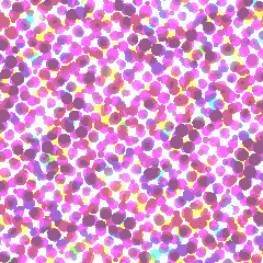
PL. 117 · COLOUR / SCREEN / AMPLITUDE MODULATION
AM Halftone Screen
W. H. Fox Talbot, 1852 · commercial screens by Frederic Ives and the Levy brothers, 1880s-90s
OPEN THE LIVE PLATE ▸DEFINITION
K = 1 − max(R,G,B)
(C,M,Y) = (1−R−K, 1−G−K, 1−B−K) / (1−K)
per screen (θ = 15°, 75°, 0°, 45°): r = ½·cell·√coverage
NOTES
Talbot patented breaking a photographic tone into a screen of dots in 1852, using a piece of gauze held between the negative and the plate; Ives, and then Ives working alongside the Levy brothers, spent the 1880s and 1890s turning that proposal into a ruled glass screen precise enough to print a magazine page from. What all of them built is amplitude modulation: a halftone screen prints only solid ink, yet the picture reads as continuous tone because each ink is broken into a fine grid of round dots whose size, not their density, carries the tone — against the frequency-modulated stochastic screens some digital workflows use instead. Where bayer and errordiff decide, pixel by pixel, whether to switch a single ink fully on, this plate grows one dot per screen cell continuously from nothing to a disc that very nearly fills its cell — the coverage sampled at that cell becomes the dot radius directly, not a threshold decision. Reproducing colour needs four such screens, one per process ink, and ruling all four at the same angle would stack every dot on its neighbours, printing a coarse grid rather than a photograph. Cyan, magenta and black are staggered 15, 75 and 45 degrees apart — 30 degrees from one another, the widest spacing three screens can share on a grid whose own symmetry repeats every 90 degrees — and yellow, whose pale ink shows almost no visible beat, is left at 0 degrees, the angle the other three could not spare among themselves. Overlay the four and the small, even flower of dots that results is not a flaw: it is exactly the interference plate 83 shows directly between two rotated gratings, tuned here so the beat resolves into a rosette rather than an ugly one. A pure round dot also has a ceiling: the largest circle that fits inside a cell without touching its neighbours covers only π/4, about 79 percent, of that cell, so a nominal full tone still leaves the four corners of every cell bare. Real halftone separations solve this by growing the dot into a square and then a diamond past that point; this plate keeps the textbook round spot function across its whole range and lets that ceiling show.
PROVENANCE
- Origin
- W. H. Fox Talbot, British patent, photoglyphic engraving, 1852 — a gauze screen breaking a photographic tone into printable dots. Frederic E. Ives, halftone relief process, 1881, and the crossline screen, 1885 (two ruled screens cemented crossed with Canada balsam). Louis E. Levy and Max Levy, US Patent 521,659, Screen for Half-Tone Process, 21 February 1893 — precision-ruled glass screens manufactured at commercial scale
- Standing
- Public domain — a 19th-century British patent and two expired 19th-century US patents, all long out of term
- Screen angles
- The specific C15/M75/Y0/K45 convention used here is printing-industry practice accumulated across the 20th century, not the product of one paper or patent, so it is not sourced to an author. The geometry behind it is derivable and stated in the note rather than credited: a periodic dot grid repeats every 90 degrees, three screens spread maximally at 30 degrees apart within that symmetry, and a fourth cannot join them without landing on top of one — yellow, the least visible ink, is the one given the leftover angle
- Rendering
- Print halftone is subtractive against white paper, not additive against black, so this plate renders as ink on a plain white sheet rather than the near-black ground most plates here use — a deliberate exception, not an inconsistency. The ramp warning about sparse marks losing themselves in the dark trough governs marks, and does not apply to a continuous field whose whole subject is what ink on paper looks like
- Constants
- freq is a count — lines across the plate — the same reasoning as moire pitch and the optics scanN dial, not a pixel size. gain is a gamma on coverage (coverage^(1/gain)): 1 is neutral, above 1 grows midtones the way ink spreading on paper does, below 1 shrinks them. scale sets the ring count in the underlying test image and carries no print-technology meaning of its own — it exists only so the screens have a picture with real spatial structure to separate
TOUCHDESIGNER · GLSL
The same shader this plate runs, reframed for a GLSL TOP. Pasted bare it renders the published constants as a still frame; wire absTime.seconds into u_t on the Vectors page to animate it.
// FORMA — PL. 117 · AM HALFTONE SCREEN — W. H. Fox Talbot, 1852 · commercial screens by Frederic Ives and the Levy brothers, 1880s-90s
//   K = 1 − max(R,G,B)
//   (C,M,Y) = (1−R−K, 1−G−K, 1−B−K) / (1−K)
//   per screen (θ = 15°, 75°, 0°, 45°): r = ½·cell·√coverage
// TouchDesigner port — paste into a GLSL TOP's pixel shader. Set the
// resolution on the TOP's Common page. As pasted it renders the published
// constants as a still frame; to animate, add a uniform named u_t on the
// GLSL TOP's Vectors 1 page with the expression absTime.seconds.
// Constants are consts — edit to tweak; comments give the measured range.
// Written from the published mathematics, not adapted from any code.

#define u_res (uTDOutputInfo.res.zw)
uniform float u_t;               // absTime.seconds on the Vectors page; unset = still

const float u_phase = 0.4358;    // this plate's own grid phase, 0..1
// FORMA's COLOUR accent as cosine-gradient coefficients
const vec3 u_pal_a = vec3(0.46, 0.2002, 0.3896);
const vec3 u_pal_b = vec3(0.5, 0.2176, 0.4235);
const vec3 u_pal_c = vec3(1, 1, 1);
const vec3 u_pal_d = vec3(0, 0.05, 0.1);

const float p_freq  = 20.0;        // lines across the plate · live 8 .. 48
const float p_gain  = 1.15;        // dot gain · live 0.5 .. 2.4
const float p_scale = 8.0;         // test image rings · live 2 .. 24

/* The order's ramp — the same cosine formulation the JS kit uses, so a
   plate keeps its classification colour in either language. */
vec3 ramp(float t){
  return clamp(u_pal_a + u_pal_b * cos(6.28318530718 * (u_pal_c * t + u_pal_d)), 0.0, 1.0);
}

/* Sawtooth and triangle on this plate's phase, mirroring the JS kit. */
float cycle(float t, float period){ return fract(t / period + u_phase); }
float pingpong(float t, float period){
  float u = cycle(t, period);
  return u < 0.5 ? u * 2.0 : 2.0 - u * 2.0;
}


/* Naive subtractive separation — the same formula the JS path uses. */
vec4 halftone_cmyk(vec3 rgb){
  float k = 1.0 - max(rgb.r, max(rgb.g, rgb.b));
  float denom = max(0.0001, 1.0 - k);
  return vec4((1.0 - rgb.r - k) / denom, (1.0 - rgb.g - k) / denom, (1.0 - rgb.b - k) / denom, k);
}

/* The continuous test image: a slow spiral of rings drawn from the cosine
   ramp this order already uses. */
vec3 halftone_scene(vec2 uv, float ar, float scaleN, float drift){
  vec2 p = vec2(uv.x - 0.5, (uv.y - 0.5) * ar);
  float r = length(p);
  float a = atan(p.y, p.x);
  float field = 0.5 + 0.42 * sin(r * scaleN * 6.283185307179586 - drift * 6.283185307179586 + a * 3.0);
  return ramp(field);
}

/* Rotate into the screen space for this channel, find the cell this
   fragment falls in, and resample the scene once at the centre of that
   cell — the textbook AM-screening step, done per-fragment because a
   fragment shader has no separate pass to precompute it in (the JS path
   does; see the header for why the two bodies differ here without showing
   a different picture). dist comes back in cell units, 0 at the centre. */
vec4 halftone_cell(vec2 uv, float ar, float angleDeg, float bearing, float freq,
                    float scaleN, float drift, out float dist){
  float th = angleDeg * 3.141592653589793 / 180.0 + bearing;
  float co = cos(th), si = sin(th);
  vec2 p = vec2(uv.x - 0.5, (uv.y - 0.5) * ar);
  vec2 r = vec2(p.x * co + p.y * si, -p.x * si + p.y * co);
  vec2 c = r * freq;
  vec2 cell = floor(c);
  vec2 f = c - cell - 0.5;
  dist = length(f);
  vec2 cc = (cell + 0.5) / freq;
  vec2 centre = vec2(cc.x * co - cc.y * si, cc.x * si + cc.y * co);
  vec2 su = vec2(centre.x + 0.5, centre.y / ar + 0.5);
  return halftone_cmyk(halftone_scene(su, ar, scaleN, drift));
}

/* Coverage grown into the classic round spot function — see the header for
   the pi/4 ceiling this deliberately does not work around. */
float halftone_ink(float value, float gainExp, float dist){
  float coverage = clamp(pow(clamp(value, 0.0, 1.0), gainExp), 0.0, 1.0);
  float radius = 0.5 * sqrt(coverage);
  return dist < radius ? 1.0 : 0.0;
}

vec3 plate(vec2 uv){
  float ar = u_res.y / u_res.x;
  float bearing = u_phase * 6.283185307179586;
  float gainExp = 1.0 / p_gain;
  float drift = u_t * 0.05;

  float distC, distM, distY, distK;
  vec4 cmykC = halftone_cell(uv, ar, 15.0, bearing, p_freq, p_scale, drift, distC);
  vec4 cmykM = halftone_cell(uv, ar, 75.0, bearing, p_freq, p_scale, drift, distM);
  vec4 cmykY = halftone_cell(uv, ar,  0.0, bearing, p_freq, p_scale, drift, distY);
  vec4 cmykK = halftone_cell(uv, ar, 45.0, bearing, p_freq, p_scale, drift, distK);

  float inkC = halftone_ink(cmykC.x, gainExp, distC);
  float inkM = halftone_ink(cmykM.y, gainExp, distM);
  float inkY = halftone_ink(cmykY.z, gainExp, distY);
  float inkK = halftone_ink(cmykK.w, gainExp, distK);

  float r = (1.0 - inkC) * (1.0 - inkK);
  float g = (1.0 - inkM) * (1.0 - inkK);
  float b = (1.0 - inkY) * (1.0 - inkK);
  return vec3(r, g, b);
}

out vec4 fragColor;
void main(){
  // FORMA's uv runs y-down, matching its canvas; TD's vUV runs up
  vec2 uv = vec2(vUV.s, 1.0 - vUV.t);
  fragColor = TDOutputSwizzle(vec4(plate(uv), 1.0));
}
NUKE · BLINKSCRIPT
The same shader this plate runs, transpiled to a BlinkScript kernel. Paste it into a BlinkScript node's Kernel Source and press Recompile; every constant arrives as a knob at its published value, and u_t animates with the expression frame/24. Compiled and rendered in Nuke 17.1, then compared against this plate on the page.
// FORMA — PL. 117 · AM HALFTONE SCREEN — W. H. Fox Talbot, 1852 · commercial screens by Frederic Ives and the Levy brothers, 1880s-90s
//   K = 1 − max(R,G,B)
//   (C,M,Y) = (1−R−K, 1−G−K, 1−B−K) / (1−K)
//   per screen (θ = 15°, 75°, 0°, 45°): r = ½·cell·√coverage
// Nuke port — a BlinkScript kernel. Paste into a BlinkScript node's Kernel
// Source and press Recompile. Every constant arrives as a knob at its published
// value (the comment gives the measured range); u_t is a knob too — animate it
// with the expression frame/24 or leave it at 0 for the still frame. Written
// from the published mathematics, not adapted from any code.
// Transpiled from the shader this plate runs on the page (GLSL ES 3.00):
// vec → float2/3/4, swizzles expanded, GLSL builtins Blink lacks written out
// as forma_ functions, float literals suffixed. Compiled and rendered in a
// real Nuke (17.1v1) and compared against this plate on the page: 34 of 34.
//
// plate() and its helpers are written to a single exit — the loop that runs
// once. That is not a style: Blink 17.1 drops a conditional early return from
// a called function while Vectorize is on, which is the node default, with no
// warning and no error. Written this way it paints correctly as pasted.

kernel Forma_halftone : ImageComputationKernel<ePixelWise>
{
  Image<eWrite> dst;

param:
  float u_t;             // seconds; 0 is the still frame
  float p_freq;  // lines across the plate · live 8 .. 48
  float p_gain;  // dot gain · live 0.5 .. 2.4
  float p_scale; // test image rings · live 2 .. 24

local:
  float2 u_res;
  float u_phase;
  float3 u_pal_a, u_pal_b, u_pal_c, u_pal_d;

  void define(){
    defineParam(u_t, "u_t", 0.0f);
    defineParam(p_freq, "p_freq", 20.0f);
    defineParam(p_gain, "p_gain", 1.15f);
    defineParam(p_scale, "p_scale", 8.0f);
  }

  void init(){
    u_res = float2(float(dst.bounds.width()), float(dst.bounds.height()));
    u_phase = 0.4358f;    // this plate's own grid phase, 0..1
    // FORMA's COLOUR accent as cosine-gradient coefficients
    u_pal_a = float3(0.46f, 0.2002f, 0.3896f);
    u_pal_b = float3(0.5f, 0.2176f, 0.4235f);
    u_pal_c = float3(1.0f, 1.0f, 1.0f);
    u_pal_d = float3(0.0f, 0.05f, 0.1f);
  }

  /* GLSL builtins Blink lacks, written as templates rather than overload sets.
     Blink's operators return expression templates (Swizzle<float,N>), so a call
     passing an expression cannot resolve against an overload set on float2
     against float3 — measured in Nuke 17.1: a float2 expression is ambiguous
     between the two, while scalar-against-vector resolves. A template deduces
     the expression's own type, so the ambiguity cannot arise. */
  template <class T> T forma_fract(T v){ return v - floor(v); }
  template <class T, class S> T forma_mod(T x, S y){ return x - y * floor(x / y); }
  /* Blink's own min/max/clamp take no scalar bound against a vector, which GLSL
     does; v * 0.0f + b is that bound at the vector's own width, and collapses to
     b when v is a scalar, so one template serves both. */
  template <class T, class S> T forma_min(T a, S b){ return min(a, a * 0.0f + b); }
  template <class T, class S> T forma_max(T a, S b){ return max(a, a * 0.0f + b); }
  template <class T, class S> T forma_clamp(T v, S lo, S hi){ return clamp(v, v * 0.0f + lo, v * 0.0f + hi); }
  int forma_min(int a, int b){ return min(a, b); }
  int forma_max(int a, int b){ return max(a, b); }
  /* GLSL step(edge, x) is 1 where x >= edge; floor(sign(x - e) * 0.5 + 1) is
     that exactly, equality included, out of builtins Blink does have. */
  template <class T, class S> T forma_step(S e, T x){ return floor(sign(x - e) * 0.5f + 1.0f); }
  template <class T, class S> T forma_smoothstep(S a, S b, T x){
    T t = forma_clamp((x - a) / (b - a), 0.0f, 1.0f);
    return t * t * (3.0f - 2.0f * t);
  }
  template <class T> float forma_distance(T a, T b){ return length(a - b); }
  float forma_tanh(float x){ float e = exp(2.0f * x); return (e - 1.0f) / (e + 1.0f); }
  float forma_radians(float d){ return d * 0.01745329252f; }
  // the page's hash2 is exact uint32; Blink has int, so the shifts are made
  // logical by masking and the read-back is lifted into 0 .. 2^32
  /* A uint read back as a float. Blink has no unsigned type, so a value past
     2^31 arrives as a negative int and float() of it is negative. Measured on
     gabor, whose own generator then returned uniforms in [-0.5, 0.5) and drew
     a different picture — it compiled, it rendered, and only comparing it with

  /* The order's ramp — the same cosine formulation the JS kit uses, so a
     plate keeps its classification colour in either language. */
  float3 ramp(float t){
    return forma_clamp(u_pal_a + u_pal_b * cos(6.28318530718f * (u_pal_c * t + u_pal_d)), 0.0f, 1.0f);
  }

  /* Sawtooth and triangle on this plate's phase, mirroring the JS kit. */
  float cycle(float t, float period){ return forma_fract(t / period + u_phase); }
  float pingpong(float t, float period){
    float u = cycle(t, period);
    return u < 0.5f ? u * 2.0f : 2.0f - u * 2.0f;
  }


  /* Naive subtractive separation — the same formula the JS path uses. */
  float4 halftone_cmyk(float3 rgb){
    float k = 1.0f - forma_max(rgb.x, forma_max(rgb.y, rgb.z));
    float denom = forma_max(0.0001f, 1.0f - k);
    return float4((1.0f - rgb.x - k) / denom, (1.0f - rgb.y - k) / denom, (1.0f - rgb.z - k) / denom, k);
  }

  /* The continuous test image: a slow spiral of rings drawn from the cosine
     ramp this order already uses. */
  float3 halftone_scene(float2 uv, float ar, float scaleN, float drift){
    float2 p = float2(uv.x - 0.5f, (uv.y - 0.5f) * ar);
    float r = length(p);
    float a = atan2(p.y, p.x);
    float field = 0.5f + 0.42f * sin(r * scaleN * 6.283185307179586f - drift * 6.283185307179586f + a * 3.0f);
    return ramp(field);
  }

  /* Rotate into the screen space for this channel, find the cell this
     fragment falls in, and resample the scene once at the centre of that
     cell — the textbook AM-screening step, done per-fragment because a
     fragment shader has no separate pass to precompute it in (the JS path
     does; see the header for why the two bodies differ here without showing
     a different picture). dist comes back in cell units, 0 at the centre. */
  float4 halftone_cell(float2 uv, float ar, float angleDeg, float bearing, float freq,
                      float scaleN, float drift, float& dist){
    float th = angleDeg * 3.141592653589793f / 180.0f + bearing;
    float co = cos(th);
    float si = sin(th);
    float2 p = float2(uv.x - 0.5f, (uv.y - 0.5f) * ar);
    float2 r = float2(p.x * co + p.y * si, -p.x * si + p.y * co);
    float2 c = r * freq;
    float2 cell = floor(c);
    float2 f = c - cell - 0.5f;
    dist = length(f);
    float2 cc = (cell + 0.5f) / freq;
    float2 centre = float2(cc.x * co - cc.y * si, cc.x * si + cc.y * co);
    float2 su = float2(centre.x + 0.5f, centre.y / ar + 0.5f);
    return halftone_cmyk(halftone_scene(su, ar, scaleN, drift));
  }

  /* Coverage grown into the classic round spot function — see the header for
     the pi/4 ceiling this deliberately does not work around. */
  float halftone_ink(float value, float gainExp, float dist){
    float coverage = forma_clamp(pow(forma_clamp(value, 0.0f, 1.0f), gainExp), 0.0f, 1.0f);
    float radius = 0.5f * sqrt(coverage);
    return dist < radius ? 1.0f : 0.0f;
  }

  float3 plate(float2 uv){
    float ar = u_res.y / u_res.x;
    float bearing = u_phase * 6.283185307179586f;
    float gainExp = 1.0f / p_gain;
    float drift = u_t * 0.05f;

    float distC;
    float distM;
    float distY;
    float distK;
    float4 cmykC = halftone_cell(uv, ar, 15.0f, bearing, p_freq, p_scale, drift, distC);
    float4 cmykM = halftone_cell(uv, ar, 75.0f, bearing, p_freq, p_scale, drift, distM);
    float4 cmykY = halftone_cell(uv, ar,  0.0f, bearing, p_freq, p_scale, drift, distY);
    float4 cmykK = halftone_cell(uv, ar, 45.0f, bearing, p_freq, p_scale, drift, distK);

    float inkC = halftone_ink(cmykC.x, gainExp, distC);
    float inkM = halftone_ink(cmykM.y, gainExp, distM);
    float inkY = halftone_ink(cmykY.z, gainExp, distY);
    float inkK = halftone_ink(cmykK.w, gainExp, distK);

    float r = (1.0f - inkC) * (1.0f - inkK);
    float g = (1.0f - inkM) * (1.0f - inkK);
    float b = (1.0f - inkY) * (1.0f - inkK);
    return float3(r, g, b);
  }

  void process(int2 pos){
    // FORMA's uv runs y-down like its canvas; Nuke's rows run up
    float2 uv = float2((float(pos.x) + 0.5f) / u_res.x, 1.0f - (float(pos.y) + 0.5f) / u_res.y);
    float3 c = plate(uv);
    dst() = float4(c.x, c.y, c.z, 1.0f);
  }
};