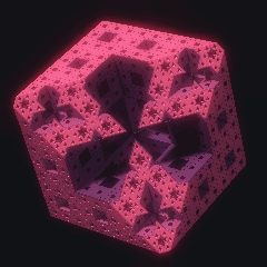
PL. 147 · FRACTALS / DISTANCE FIELD / TERNARY RULE
Menger Sponge
Karl Menger, 1926
OPEN THE LIVE PLATE ▸DEFINITION
divide [−½,½]³ into 3×3×3, remove a subcube when two or more of
its ternary digits read 1 at the same level, recurse
N(n) = 20ⁿ cells of side 3⁻ⁿ, volume(n) = (20/27)ⁿ, dim_H = log 20 / log 3 ≈ 2.7268
d(p) = max( sdBox(p), 3⁻⁽ᵏ⁺¹⁾·reach_k(p), p·â − s )
sphere trace: t → t + d(o + t·û);  n = ∇d / |∇d|
NOTES
Karl Menger set down the whole family of these objects in 1926 with one recursive rule, and the sponge is a single case of it: divide a cube into twenty-seven equal parts on a three-by-three-by-three grid, discard the seven that sit centred on a face or on the whole cube, and repeat inside each of the twenty survivors forever. Written in ternary digits the discard rule reads plainly: remove a subcube the moment two or more of its three coordinate digits equal one at the same recursion level — three coordinates instead of two, and two-of-three instead of two-of-two, is the entire distance from the sierpinski carpet two plates over (PL. 107) to this. What remains has volume zero and Hausdorff dimension log 20 over log 3, about 2.7268, the solid counterpart to the log 8 over log 3 of the carpet. The 1926 paper does not stop at three dimensions: it defines a whole scale of curves at every dimension and every codimension at once, with the carpet and this sponge as two named cases among infinitely many. What this plate draws is the solid itself, lit, found by marching rays at it — and then cut open by a plane, because the section is half of what there is to see. The march needs a distance to the surface, and for this object the distance is exact rather than estimated. At every level the sponge is contained in the union of that level cells that the rule keeps, so the distance to the nearest kept cell is a lower bound on the distance to the sponge, which is all a sphere trace asks for. Leaving the middle third along one axis changes that one ternary digit and nothing else, the three axes are perpendicular, so the nearest cell on the far side of the rule is reached by clearing the cheapest crossings the rule requires and the cost of that is their Euclidean norm — a real distance, so it is Lipschitz with constant one, and Hart guarantee applies to it with nothing to prove about a derivative. Measured against an independent branch-and-bound over the actual cells it is not merely a bound: the ratio is one at the median in every clearance band and never exceeds one anywhere in twenty thousand samples. The cutting plane is intersected with the solid rather than applied to the ray, which is the difference between a section and a hole punched in a picture: the flat face is then a genuine surface of a genuine object, its normal falls out of the same gradient every other surface uses, and the shadow and the ambient term see the object the eye sees rather than material the frame has already removed. So the reader dials two things that are the exhibit. The view axis runs from straight down a face — where the silhouette is a square and the lit face is the sierpinski carpet exactly, checked point for point against an independent implementation of the carpet rule — to the main diagonal of the cube, corner to corner, where the three edge directions project at equal length and a hundred and twenty degrees apart and the silhouette is a hexagon. That second identity is a statement about a parallel projection, and a wide lens destroys it: the rendered hexagon carries a near-to-far radius ratio that is exactly the perspective foreshortening of the throw it is seen from, 0.78 at the widest lens on the dial and 0.93 at the longest, so the lens is what recovers the figure rather than a matter of taste. The cut then travels along that axis, and on the diagonal what it opens is the six-pointed star pattern that made this object famous. That figure is not in the 1926 paper at all: it was first rendered by Sebastien Perez-Duarte in 2007 and posted to Flickr, taken up by Kenneth Chang for the New York Times in 2011 and narrated by George Hart in a Simons Foundation film the year after. Colour is the recursion level of the void nearest the surface — the plate own scheme from when it was a plane cut, coloured by the depth at which a cell fell, read from the solid side, which paints the carpet onto every outer face and tells a wide tunnel from a fine crevice. It rides a rising segment of the order palette and never crosses the dark middle of it, and on this object that is a decision with a reason rather than a house rule: spanning the trough puts the deepest solid material near black, and on a sponge black is what a removed cell looks like, so the picture would read its own subject backwards. Where the mathematics stops and the picture begins is worth saying plainly. The distance, the march, where it stops, the normal and the cutting plane are the plate. The light is not: its two directions are fixed relative to the eye and one slider turns the key around, and where a lamp stands is staging. Lambert on that normal, a halfway-vector specular, a cone traced back toward the light for the soft shadow and a hemisphere of short rays for the ambient obscurance are published models rather than invented ones, which is why they are named under Provenance and not merely used. The optics of the page run after all of it and outside this function entirely, as they do over every plate here. The camera does not move, and it cannot: rendering this way is far more than one frame holds, so the picture develops instead — every paint traces a batch of rays into a buffer, coarsest first, the first paint laying down a whole eighth-resolution picture and later ones refining it until every cell has been traced once. A camera move would throw all of that away, so the view is constants the reader turns rather than an animation, and turning one restarts a development that takes about a sixth of a second. The shader does the same march in one frame at full resolution and arrives at the same picture, and that it is the same picture is measured under Provenance rather than assumed. One thing about the recursion depth is worth knowing before touching it, because it is not the dial it looks like. A ray spends its life outside the solid, where the descent stops at the first level that removes the cell it is standing in, so it almost never pays for the levels below; the whole range from 2 to 6 spans nine tenths of a millisecond a batch at a card and one and a third at the drawer — and it keeps changing the picture at every step, better than a fifth of the frame at each of them, which is why it is neither locked nor a quality dial. Past depth 4 the new cells are finer than a card can sample and only the shader at full resolution and the export ever resolve them.
PROVENANCE
- Origin
- K. Menger, "Allgemeine Raume und Cartesische Raume. I.", Proceedings of the Section of Sciences, Koninklijke Akademie van Wetenschappen te Amsterdam 29, 1926, pages 476 to 482. Pre-DOI, so this entry links nothing that cannot instead be checked directly: the volume, page range and title were confirmed again for this wave against an independent reprint listing (Menger, Selecta Mathematica I, which collects the paper), not taken on an earlier record alone
- The one it is not
- A different, earlier Menger paper is sometimes cited for the sponge instead: "Uber die Dimensionalitat von Punktmengen", Monatshefte fur Mathematik und Physik 33, 1923, pages 148 to 160, with a second part in 1924. That pair is dimension theory. Neither constructs the sponge, the carpet, or any member of the family below, and neither is cited here for that reason
- The type-k family, and where the sponge sits in it
- The 1926 paper defines, in a single stroke, an entire scale of curves at every dimension n and every type k. In that notation the sierpinski carpet drawn at PL. 107 is the case n equals 2, k equals 1; the sponge drawn here is n equals 3, k equals 1; the fully disconnected Cantor dust that keeps only the eight corner cells at every level, with no face-centre or body-centre removal at all, is the case k equals 0. Rob Hocking, writing for the Bridges Mathematical Art conference in 2023 (pages 291 to 298; Bridges assigns no DOI to any paper, read directly for this entry rather than taken on the brief record), restates the standard three-dimensional sponge in exactly the digit form this plate implements: a point (x, y, z) belongs to the sponge exactly when, at every ternary digit position, the count of coordinates whose digit there reads one is at most one -- equivalently, a subcube is discarded the moment two or more of its three digits equal one at the same level, which is the rule coded below and checked digit for digit against that formula in the harness
- Standing
- Public domain since 1926. No patent has ever applied to a recursive subdivision of a cube. The rendering method is published literature of the same standing: sphere tracing, Lambert, Blinn and the ambient obscurance model are all papers, and none of them is or ever was encumbered
- The slice measure, the src link, and why it survived the change of renderer
- The src identifier is not the origin paper, gyroid fashion -- it names a specific later claim about slicing rather than the construction itself. T. Kempton, "Sets of beta-expansions and the Hausdorff measure of slices through fractals", Journal of the European Mathematical Society 18(2), 2016, pages 327 to 351 (doi:10.4171/JEMS/591, re-verified for this wave against the live Crossref record: title, sole author Kempton, volume 18, issue 2, pages 327 to 351, published 2016-02-08, all matching). Its Example 1 takes the Menger sponge as the illustration: for almost every plane -- in the sense of the natural measure on planes at a fixed distance and orientation -- the intersection with the sponge carries positive, finite Hausdorff measure in dimension (log 20 / log 3) minus 1. That is a statement about almost every orientation and offset taken together, not about either named extreme this plate dials to, and nothing here claims otherwise. This citation was put back on the table when the plate stopped being a plane cut, because a lit solid seen down its own diagonal is a PROJECTION and not a section, and Kempton says nothing about projections. Two honest answers existed. One was to drop src and leave the plate linkless, which is the correct state for a 1704-and-1926 origin and would have cost nothing. The other was to make the picture rest on a section again, which is what happened: the near plane is intersected with the solid, so the flat face of what is drawn IS the intersection of the sponge with a plane, and at the default constants that face is most of the frame. The claim and the picture are back in step, and the decision is recorded here rather than left as an inherited link nobody re-read. If a later edition removes the cut, this identifier goes with it
- The hexagram, honestly
- Sebastien Perez-Duarte discovered the diagonal slice by rendering it, and posted the result, titled "Slice of Menger", to Flickr in 2007. Kenneth Chang wrote it up as "The Mystery of the Menger Sponge" for the New York Times on 28 June 2011, and George Hart narrated "Mathematical Impressions: The Surprising Menger Sponge Slice" for the Simons Foundation on 10 December 2012 -- all three read or fetched directly for this entry rather than taken on trust, the New York Times page confirmed only by address since the live site returns 403 to an automated fetch. The first refereed treatment of the slice family is the Hocking paper cited above, which names the same 2007 discovery and the same two popular accounts in its own references before generalising the construction to four dimensions. No source read for this entry attaches a Hausdorff dimension figure to the hexagram slice specifically; where a number circulates online it traces to informal posts rather than to a refereed source, and none is stated here
- The rendering, and every part of it named
- The march is sphere tracing: J. C. Hart, "Sphere tracing: a geometric method for the antialiased ray tracing of implicit surfaces", The Visual Computer 12(10), 1996, 527-545, doi:10.1007/s003710050084. Given a function returning a lower bound on the distance to the surface, step by exactly that bound; each evaluation defines an unbounding sphere guaranteed to contain no intersection, so no step can penetrate. The soft shadow is section 5 of the same paper, not a folk trick: marching toward the light, the unbounding sphere of radius d at distance t subtends a half-angle whose sine is d/t, so the running minimum of that ratio bounds how much of the light cone is still visible. The lineage of distance-bounded marching on a deterministic fractal is J. C. Hart, D. J. Sandin and L. H. Kauffman, "Ray tracing deterministic 3-D fractals", ACM SIGGRAPH Computer Graphics 23(3), 1989, 289-296, doi:10.1145/74334.74363 -- named for the method, and explicitly NOT for the estimate, which there is the Douady-Hubbard form for a squaring map and here is an exact Euclidean distance to a union of boxes. Shading: Lambert, Photometria, 1760, pre-DOI and public domain, of which the whole content here is max(0, n dot l); the specular is the halfway vector of J. F. Blinn, "Models of light reflection for computer synthesized pictures", Proceedings of SIGGRAPH 77, 192-198, doi:10.1145/563858.563893 (the exponent-on-the-reflection alternative is Bui Tuong Phong, "Illumination for computer generated pictures", Communications of the ACM 18(6), 1975, 311-317, doi:10.1145/360825.360839, and is one line either way). The ambient term is S. Zhukov, A. Iones and G. Kronin, "An ambient light illumination model", Eurographics Rendering Techniques 98, Springer 1998, 45-55, doi:10.1007/978-3-7091-6453-2_5: W(P) is the mean over the hemisphere of a monotone function of the distance to the nearest occluder, zero at zero and one at infinity, and what runs here is four cosine-weighted directions each sphere traced to a radius R with the simplest member of the family they give. It is deliberately NOT the five-tap distance-field trick that circulates as ambient occlusion in demo code: that has no published derivation, and reproducing it would be reproducing a sketch. All five identifiers were resolved against the live Crossref API for the wave and matched on title, authors, container, year and pages; Blinn 1977 carries empty volume and issue fields there, which is why it is cited as the proceedings rather than in the Computer Graphics 11(2) form a secondary source would supply
- Is the distance a bound, and how tight
- It is a bound and it is very nearly the distance itself, which is unusual enough to be worth measuring twice rather than asserting. Tested against an EXACT distance computed independently: a recursive branch and bound over the actual cells of the depth-d solid, pruned on the exact box distance, which shares no line of reasoning with the digit descent the plate runs. 4,000 exterior points at each of five depths, 20,000 in all, drawn uniformly in a box wider than the cube. The ratio of the estimate to that exact distance never exceeds 1 anywhere -- not one sample of 20,000 -- and its median is 1.0000 in every clearance band tried (under 0.01, under 0.05, and beyond), so the estimate is not merely conservative, it is EQUAL to the distance almost everywhere. Its mean sits at 0.988 to 0.991 because far outside the cube the box distance is the one that carries, and out there the cube boundary is nearer than the sponge. Interior points were checked separately, against the clearance found by bisection along 26 directions: worst |d| over that clearance is 1.0000 at depths 3 and 4, 1,500 interior points each, and no interior point ever returned a non-negative distance. Then the march itself, which is the unbiased test: 84,332 rays at five camera settings spanning both named views and both ends of the depth dial, 564,788 full steps, every step subdivided twelve ways and every sub-point tested for membership of the same depth-d solid -- 6.8 million membership tests, ZERO penetrating steps. The march is short because the bound is tight: the median ray finishes in 3 to 6 steps and the 99th percentile in 14 to 37
- The framing, which is computed rather than measured
- The camera sits at a distance derived from how wide the sponge reads from where it is standing, so the object holds the same size in frame as the view axis turns and only its shape changes. That width is exact arithmetic rather than a sampled bound. The silhouette of a cube along a unit direction a is the hexagon (or, on an axis, the square) through the corners minimising |c dot a|, every corner has |c| = sqrt(3)/2, and the perpendicular radius is therefore sqrt(3/4 - (c dot a)^2); the four sign patterns of |ax +- ay +- az| are the four distinct values of |c dot a|, so four absolute values and three minima give the answer with nothing to sample. And it is the SPONGE silhouette, not merely the cube one, because the whole edge skeleton of the cube survives the digit rule at every level -- an edge point has two coordinate digits fixed at 0 or 2 and only one free, so the count of digits reading one can never reach two. Checked: 200,000 points on the twelve edges, all inside at depth 6, and all eight corners inside. The radius runs from sqrt(1/2) = 0.7071 straight down a face to sqrt(2/3) = 0.8165 down the diagonal, and the camera is placed at 1.10 of it on the frame half-height, which leaves the silhouette filling about nine tenths of the height with air around it. Looked at against 1.00, 1.05, 1.15, 1.20 and 1.25: at 1.00 the corners touch the frame edge, and past 1.20 the plate is small in its own card
- The hexagon, as a projection this time
- The plane slice measured its 120 degrees on the CUTTING PLANE; a lit solid has to make the same statement about the VIEW, and the two are different claims. Analytically, through the camera basis the plate actually builds: at view axis 1 the three edge directions of the cube project onto the image plane at lengths 0.816496580928, 0.816496580928 and 0.816496580928 -- sqrt(2/3) to twelve places, spread 2.2e-16 -- and at exactly 60 degrees to one another, ten decimal places, which as undirected axes is the 120 degrees the slice reported. The view axis itself differs from (1,1,1)/sqrt(3) by 1.1e-16, because it is the endpoint of a rotation rather than a rounded angle: the whole camera frame is carried by a rotation about (-1,1,0)/sqrt(2) through orient times 54.7356 degrees and then about the body diagonal by spin, so the identity is exact at the top of the slider and no step size can miss it. That frame stays orthonormal to 6.7e-16 and right handed over 2,525 samples of the two dials. Then the rendered picture, silhouette radius by angle about the frame centre at 700 square: six vertices, all six gaps 60.00 degrees, at every long lens tried. Their radii are NOT equal, and the amount they differ by is the finding rather than an error -- it is perspective, and it matches the closed form. Near corners sit at |c dot a| = 0.2887 and far ones at -0.2887, so the ratio of the two radii should be (throw - 0.2887)/(throw + 0.2887): measured 0.9334 against 0.9346 at lens 12, 0.9217 against 0.9241 at lens 14, 0.8664 against 0.8670 at lens 25. At the wide end the agreement breaks (0.7798 measured against 0.7133 at lens 55) because at that throw the far corners are behind nearer material and the outline stops being the cube outline at all -- which is the same fact from the other side. Straight down a face the rendered silhouette is four vertices at 90.00 degrees with 0.00 per cent radius spread, since all four corners are equidistant there and perspective has nothing to do
- Checked, not just plotted
- Five things, run against the shipped draw() and its own helpers. First, the digit rule against the volume law the construction predicts: two million uniform points classified at each of six depths reproduce (20/27) to the power of depth to within sampling noise at every one -- 0.740957 against 0.740741 at depth 1, 0.164908 against 0.165195 at depth 6. Second, the carpet identity, which is now a statement about a FACE rather than about a cut: 300,000 points of the cube +z face classified by the sponge rule at depth 6 against an independent implementation of the sierpinski carpet rule at PL. 107 (remove when BOTH digits read one), zero disagreements, 49.34 per cent kept -- so the face-on view of this solid is PL. 107 exactly, lit. Third, the six tunnels: a ray started far away along each coordinate axis through the centre of the cube finds no surface at all at depth 6, which is what bored clean through means, and the six face centres are outside the solid at depth 1 while the eight corners are inside at depth 6. Fourth, the distance and the march, above. Fifth, the two paths, below
- The colour, and why the trough is refused here
- The order palette is brightest near t = 0 and t = 1 and essentially black at t = 0.5, and the standing rule is that a sparse mark must stay in the bright lobe while a FIELD may cross the trough deliberately, mandelbrot fashion. A lit solid looks like the second case and on this object it is not, which was settled by rendering it rather than by reasoning about it. Four trough-spanning maps were rendered at the default view against four bright-lobe ones. Spanning the trough is legible -- it is graphically the strongest of the eight -- and it is wrong, because the material it puts near black is the material FURTHEST from any void, the deepest solid in the section, and on a sponge a black region is what a removed cell looks like. The picture would state its own subject backwards, and a reader would count the black star at the middle of the section as a hole. Measured the other way round as well: the map that puts the coarse levels bright and the fine ones dark drops the whole plate to a mean of 7.6 in 0..255 at a card, because almost all of the visible surface reads at a fine level. What ships is a MONOTONE segment of the bright lobe, 0.72 to 0.97, and that correction is the useful part of this note. The obvious bright-lobe span, the 0.82 to 1.12 the sibling mandelbox raymarch first shipped with, straddles the lobe own peak at 0.97: its two ends have the same luminance and its middle is brighter than either, so the mapping is not monotone and four recursion levels come out as three tones, which is why an orbit trap looks invisible on a lit surface. This measurement is what moved mandelbox onto the same rising segment afterward. Taking a rising segment of the same lobe instead moves luminance from 0.211 to 0.436, a factor of 2.07 end to end, without ever leaving it. On the plate that is the difference between one flat red and a dusky plum interior against a salmon carpet, and it is the recursion level doing the work
- What one paint can afford
- One paint cannot afford a frame of this, so a paint is a batch. The grid is capped at 500 cells across, which is 318 by 256 at a card (the card is narrower than the cap, so it renders one cell per CSS pixel) and 500 by 333 at the drawer. The batch is exactly the eighth-resolution pass -- ceil(gw/8) by ceil(gh/8) cells, or 700 rays, whichever is larger -- which makes the first paint a whole coarse picture by construction rather than by arithmetic that happens to work out. It matters: the obvious formula, cells over 64, comes out at 1,272 against an eighth pass of 1,280 at a card, and the first paint would have been a coarse picture eight rays short of finished. Measured in Chrome on this machine at the default constants: a card is 81,408 rays in 64 batches, first batch 1,280 rays, warm median 1.5 ms and 95th percentile 2.4, 123 ms in total, then 0.12 ms a frame for ever because a developed picture is a blit; the drawer at 890 by 593 is 166,500 rays, first batch 2,646, median 2.6 ms, 212 ms; a 240-square thumbnail is 57,600 rays and 121 ms; the 2048-wide export is 200,000 rays at a median of 3.4 ms. At the top of the depth dial those medians become 2.0, 3.1 and 4.7. The first paint on a cold page is 7 to 13 ms, which is the compiler rather than the march. The batch count is the constraint that decides the cap: renderStill develops an exposure over 241 draws, and a cap whose full pass needed more than that would ship a half-traced thumbnail and a half-traced export. 64 leaves it a factor of 3.8. Against the plane cut this replaced, which cost 1.05 to 2.35 ms of the same machine every frame it was visible for as long as it was visible, the solid is dearer for 64 frames and then about fifteen times cheaper
- The two rendering paths, checked
- Both paths run the same march and they are compared rather than assumed to agree, at 20 parameter tuples -- both named views, both ends of the depth dial, the widest lens, and twelve drawn at random over all six constants -- at a matched grid where the JS cap and the shader resolution are the same 400 by 322, 7,728,000 channels. As shipped the mean channel difference is 0.910 levels in 255, 8.24 per cent of channels differ by more than one, and 1.77 per cent of pixels disagree about whether they hit the surface. Bake the camera basis, the throw and the lens into the shader as the same float64 numbers the JS path computes and that falls to a mean of 0.286 with silhouette disagreement at 0.37 per cent, so most of the residue is the shader taking the sine and cosine of its own view angles at float32 and turning the camera by a fraction of a degree. What is left divides in two, and both halves were isolated rather than guessed at. Quantising the shader ramp to the eight bits the kit ramp already rounds to takes the mean from 0.181 to 0.085 on the face-on view and 0.229 to 0.141 on the three-quarter one -- that is this plate own long-standing measurement, unchanged by the new renderer. The rest sits on edges: 60 to 82 per cent of the differing pixels stand next to a luminance step of more than 20 levels, because the surfaces of this object are flat and its edges are hard, so a sub-cell difference in the ray becomes a whole flipped pixel where on a fractal-soft surface it would become a shade. Two things were ruled out. Rounding the JS digit descent to float32 -- the sample point, every tripling of it and the returned distance -- changes the picture by a mean of 0.000 and moves at most 0.001 per cent of pixels, so the digit classification is not the source and the ternary boundaries are not the hazard they look like. And the worst tuples are a geometry, not a defect: at a low view axis with a deep cut the cutting plane runs nearly parallel to a cube face, a large flat region of the sponge lies within the march stopping distance of the plane, and the normal there is decided by which of two nearly coincident planes the central difference lands on. Worst measured 12.1 per cent of pixels, and the two pictures are the same picture with one near-tangent face shaded differently
- What the shader costs, on the record
- A sphere trace at backing resolution is expensive and on a software renderer that is worth stating rather than discovering. Measured in the browser gate own Chrome forced onto ANGLE over SwiftShader, which is the machine with no GPU at all: a 318 by 256 card frame is 15.1 ms at the default depth and 17.6 at the top of the dial, against 28.1 for the sibling mandelbox, 16.9 for metamer, 3.3 for mandelbrot and 1.1 for gyroid. So this plate is the cheapest of the raymarched pair and it does not set a new worst case -- it lands just under metamer, which held the record before mandelbox arrived. At the drawer with device pixel ratio 2 it is 322 ms against mandelbox 1,203 and metamer 697. The reason it is cheap is the estimate: the median ray finishes in three to six full steps because the bound is the distance rather than a fraction of it, where a fold-based estimate returns under a third of the true clearance and pays for it in steps. The march budget follows from that and is not a slider: the picture is bit-identical from 64 steps at a card grid and from 128 at the drawer at device pixel ratio 2 (96 leaves 0.012 per cent of pixels moving at the worst setting tried), so the body carries a fixed 128 and a reader is not offered a dial whose whole travel does nothing. The reader who wants this plate cheap has GPU OFF, which puts it on the JS path at 1.5 ms a batch
- Constants, measured
- Re-swept from nothing, because five of the six constants are new or mean something different and the colouring changed -- the old numbers were void the moment the plane cut was. depth is the recursion cutoff, and it is locked nowhere because the measurement says it is neither expensive nor exhausted: batch cost across the whole range 2 to 6 is 1.10 to 2.00 ms at a card and 1.80 to 3.10 at the drawer, and each step still moves more than a fifth of the frame (18.6 per cent from 2 to 3, rising to 27.5 per cent from 5 to 6, with the mean amplitude of the change falling from 4.4 levels to 2.1 as the new cells drop below what a card can sample). A ray spends its life outside the solid, where the digit descent stops at the first level that removes the cell it is standing in, which is why the levels below cost so little. lens, orient, cut, spin and lightaz are the camera and the light and all five are free: a camera whose distance is derived from the object own silhouette cannot be jittered into looking at nothing, and the light cannot leave the object dark because it is fixed relative to the eye. params[] is a wire format and append-only once shipped, so the three constants the plane cut used -- zoom, orientation and drift -- were repurposed IN PLACE as the lens, the view axis and the cut depth, with the spin and the light azimuth appended. orient keeps both its name and its geometric meaning, since it dialled the cut normal from a face to the body diagonal and now dials the VIEW along the same arc; drift became cut, which is still an offset along that normal; zoom became lens, which is still how wide the view is. An old bench link therefore restores depth and the view axis onto the constants they meant, and lands the lens and the cut on values they never meant, which is strictly better than the silent remap that deleting entries would have caused. The liveness sweep was run twice for the same reason the constants were re-swept. As regenerate actually jitters -- all six at once, 24 seeds at two sizes over 120 frames, 5,760 renders -- 0 throws, 0 plates below the contrast floor, pixelRange worst 149 and median 177 against the gate floor of 14. Over the whole declared box instead, 40 uniform tuples at two sizes, 9,600 renders: still 0 and 0, with a worst of 53 at a fully backlit key azimuth, which is the one place the plate goes quiet and is still nearly four times the floor
- Source
- doi:10.4171/JEMS/591
TOUCHDESIGNER · GLSL
The same shader this plate runs, reframed for a GLSL TOP. Pasted bare it renders the published constants as a still frame; wire absTime.seconds into u_t on the Vectors page to animate it.
// FORMA — PL. 147 · MENGER SPONGE — Karl Menger, 1926
//   divide [−½,½]³ into 3×3×3, remove a subcube when two or more of
//   its ternary digits read 1 at the same level, recurse
//   N(n) = 20ⁿ cells of side 3⁻ⁿ, volume(n) = (20/27)ⁿ, dim_H = log 20 / log 3 ≈ 2.7268
//   d(p) = max( sdBox(p), 3⁻⁽ᵏ⁺¹⁾·reach_k(p), p·â − s )
//   sphere trace: t → t + d(o + t·û);  n = ∇d / |∇d|
// TouchDesigner port — paste into a GLSL TOP's pixel shader. Set the
// resolution on the TOP's Common page. As pasted it renders the published
// constants as a still frame; to animate, add a uniform named u_t on the
// GLSL TOP's Vectors 1 page with the expression absTime.seconds.
// Constants are consts — edit to tweak; comments give the measured range.
// Written from the published mathematics, not adapted from any code.

#define u_res (uTDOutputInfo.res.zw)
uniform float u_t;               // absTime.seconds on the Vectors page; unset = still

const float u_phase = 0.6921;    // this plate's own grid phase, 0..1
// FORMA's FRACTALS accent as cosine-gradient coefficients
const vec3 u_pal_a = vec3(0.46, 0.1389, 0.1912);
const vec3 u_pal_b = vec3(0.5, 0.151, 0.2078);
const vec3 u_pal_c = vec3(1, 1, 1);
const vec3 u_pal_d = vec3(0, 0.05, 0.1);

const float p_depth   = 4.0;         // recursion depth · live 2 .. 6
const float p_lens    = 14.0;        // lens — vertical field of view ° · live 12 .. 55
const float p_orient  = 1.0;         // view axis — face to body diagonal · live 0 .. 1
const float p_cut     = 0.35;        // section cut along the view axis · live 0 .. 0.6
const float p_spin    = 0.0;         // view spin about the diagonal ° · live -180 .. 180
const float p_lightaz = -36.0;       // key light azimuth ° · live -180 .. 180

/* The order's ramp — the same cosine formulation the JS kit uses, so a
   plate keeps its classification colour in either language. */
vec3 ramp(float t){
  return clamp(u_pal_a + u_pal_b * cos(6.28318530718 * (u_pal_c * t + u_pal_d)), 0.0, 1.0);
}

/* Sawtooth and triangle on this plate's phase, mirroring the JS kit. */
float cycle(float t, float period){ return fract(t / period + u_phase); }
float pingpong(float t, float period){
  float u = cycle(t, period);
  return u < 0.5 ? u * 2.0 : 2.0 - u * 2.0;
}


// The same march, at the canvas's own backing resolution and in one pass.
// Every helper is menger_ prefixed and nothing is declared at file scope, so
// a composition of this plate with itself still links.
float menger_reach(vec3 e, float crossings){
  float a = min(e.x, min(e.y, e.z));
  float b = max(min(e.x, e.y), min(max(e.x, e.y), e.z));
  return crossings == 2.0 ? sqrt(a * a + b * b) : a;
}
// Three bounds combined with max, which is the intersection of the three
// solids they bound: the cube, the digit rule's nearest kept cell, and the
// cutting half-space. The plane is in HERE and not on the ray, so the flat
// face is a real surface and the shadow and the obscurance see it as one.
float menger_de(vec3 pos, vec3 ax, float cutS, out float trap){
  float d = floor(p_depth + 0.5);
  vec3 q = abs(pos) - 0.5;
  float dbox = length(max(q, 0.0)) + min(max(q.x, max(q.y, q.z)), 0.0);
  vec3 f = clamp(pos + 0.5, 0.0, 0.9999995);
  float cell = 1.0, solid = 4.0, lev = 0.0, inner = -4.0, removed = 0.0;
  // 6 is the declared ceiling of p_depth -- mandelbrot fashion: a constant
  // loop bound at the slider's own maximum, breaking on the live value.
  for (int k = 0; k < 6; k++){
    if (float(k) >= d) break;
    f *= 3.0;
    cell /= 3.0;
    vec3 i3 = floor(f);
    float ones = float(i3.x == 1.0) + float(i3.y == 1.0) + float(i3.z == 1.0);
    if (ones >= 2.0){
      vec3 e = vec3(i3.x == 1.0 ? min(f.x - 1.0, 2.0 - f.x) : 4.0,
                    i3.y == 1.0 ? min(f.y - 1.0, 2.0 - f.y) : 4.0,
                    i3.z == 1.0 ? min(f.z - 1.0, 2.0 - f.z) : 4.0);
      inner = menger_reach(e, ones - 1.0) * cell;
      lev = float(k); removed = 1.0; break;
    }
    vec3 g = vec3(i3.x == 1.0 ? 4.0 : (i3.x == 0.0 ? 1.0 - f.x : f.x - 2.0),
                  i3.y == 1.0 ? 4.0 : (i3.y == 0.0 ? 1.0 - f.y : f.y - 2.0),
                  i3.z == 1.0 ? 4.0 : (i3.z == 0.0 ? 1.0 - f.z : f.z - 2.0));
    float toVoid = menger_reach(g, 2.0 - ones) * cell;
    if (toVoid < solid){ solid = toVoid; lev = float(k); }
    f -= i3;
  }
  if (removed == 0.0) inner = -solid;
  trap = lev;
  return max(max(dbox, inner), dot(pos, ax) - cutS);
}
vec3 menger_rot(vec3 v, vec3 u, float c, float s){
  return v * c + cross(u, v) * s + u * (dot(u, v) * (1.0 - c));
}
float menger_eps(float tt, float pxa){ return max(2.0e-6, 0.25 * tt * pxa); }
float menger_march(vec3 ro, vec3 rd, vec3 ax, float cutS, float t0, float t1, float pxa, out float trap){
  float tt = t0, hit = -1.0;
  trap = 0.0;
  for (int i = 0; i < 128; i++){
    float tr;
    float dd = menger_de(ro + rd * tt, ax, cutS, tr);
    if (dd < menger_eps(tt, pxa)){ trap = tr; hit = tt; break; }
    tt += dd;
    if (tt > t1) break;
  }
  return hit;
}
vec3 menger_normal(vec3 pos, vec3 ax, float cutS, float e){
  float tr;
  float gx = menger_de(pos + vec3(e, 0.0, 0.0), ax, cutS, tr) - menger_de(pos - vec3(e, 0.0, 0.0), ax, cutS, tr);
  float gy = menger_de(pos + vec3(0.0, e, 0.0), ax, cutS, tr) - menger_de(pos - vec3(0.0, e, 0.0), ax, cutS, tr);
  float gz = menger_de(pos + vec3(0.0, 0.0, e), ax, cutS, tr) - menger_de(pos - vec3(0.0, 0.0, e), ax, cutS, tr);
  return normalize(vec3(gx, gy, gz));
}
float menger_shadow(vec3 pos, vec3 l, vec3 ax, float cutS, float t0, float t1){
  float k = 1.0, tt = t0;
  for (int i = 0; i < 16; i++){
    float tr;
    float dd = menger_de(pos + l * tt, ax, cutS, tr);
    if (dd < 2.0e-6){ k = 0.0; break; }
    k = min(k, 11.0 * dd / tt);
    tt += dd;
    if (tt > t1) break;
  }
  return clamp(k, 0.0, 1.0);
}
float menger_obscurance(vec3 pos, vec3 n, vec3 ax, float cutS, float e, float R){
  vec3 u0 = vec3(0.0, 1.0, 0.0);
  if (abs(n.y) > 0.9) u0 = vec3(1.0, 0.0, 0.0);
  vec3 tg = normalize(cross(n, u0));
  vec3 bt = cross(n, tg);
  float sum = 0.0;
  for (int i = 0; i < 4; i++){
    float fi = (float(i) + 0.5) / 4.0;
    float rr = sqrt(fi), ph = float(i) * 2.39996323;
    vec3 dd = normalize(tg * (rr * cos(ph)) + bt * (rr * sin(ph)) + n * sqrt(max(0.0, 1.0 - fi)));
    float tt = 2.0 * e, hit = R;
    for (int q = 0; q < 6; q++){
      float tr;
      float s = menger_de(pos + dd * tt, ax, cutS, tr);
      if (s < e){ hit = tt; break; }
      tt += max(s, e);
      if (tt >= R){ hit = R; break; }
    }
    sum += min(1.0, hit / R);
  }
  return sum / 4.0;
}
vec3 plate(vec2 uv){
  float DEG = 0.017453292519943295;
  float BOUND = 0.8660254037844386;
  float d = floor(p_depth + 0.5);
  // Two rotations carry the whole camera frame, so nothing degenerates and
  // the body diagonal is exact at the top of the orient slider.
  float th = p_orient * 0.9553166181245093;
  vec3 a0 = vec3(-0.7071067811865476, 0.7071067811865476, 0.0);
  vec3 dg = vec3(0.5773502691896258, 0.5773502691896258, 0.5773502691896258);
  float ct = cos(th), st = sin(th);
  float sp = p_spin * DEG, cs = cos(sp), sn = sin(sp);
  vec3 AX = menger_rot(menger_rot(vec3(0.0, 0.0, 1.0), a0, ct, st), dg, cs, sn);
  vec3 UPv = menger_rot(menger_rot(vec3(0.0, 1.0, 0.0), a0, ct, st), dg, cs, sn);
  vec3 RTv = menger_rot(menger_rot(vec3(1.0, 0.0, 0.0), a0, ct, st), dg, cs, sn);
  // The exact silhouette radius from this direction: the four sign patterns
  // are the four distinct |corner . AX|, and every corner has |c| = sqrt(3)/2.
  float m1 = abs(AX.x + AX.y + AX.z), m2 = abs(AX.x + AX.y - AX.z);
  float m3 = abs(AX.x - AX.y + AX.z), m4 = abs(AX.x - AX.y - AX.z);
  float mm = min(min(m1, m2), min(m3, m4));
  float silh = sqrt(0.75 - 0.25 * mm * mm);
  float htan = tan(0.5 * p_lens * DEG);
  float dist = silh * 1.1 / htan;
  vec3 ro = AX * dist;
  vec3 fw = -AX;
  float cutS = BOUND * (1.0 - 2.0 * p_cut);

  float la = p_lightaz * DEG;
  vec3 kc = vec3(sin(la) * 0.7762, 0.6305, -cos(la) * 0.7762);
  vec3 key = RTv * kc.x + UPv * kc.y + fw * kc.z;
  vec3 fil = RTv * 0.9048 + UPv * -0.2088 + fw * -0.3712;

  float asp = u_res.x / u_res.y;
  float pxa = 2.0 * htan / u_res.y;
  float sx = uv.x * 2.0 - 1.0, sy = 1.0 - uv.y * 2.0;
  vec3 rd = normalize(fw + RTv * (sx * htan * asp) + UPv * (sy * htan));

  vec3 col = vec3(4.0, 6.0, 10.0) / 255.0;
  float bq = dot(ro, rd);
  float cq = dot(ro, ro) - 0.75;
  float disc = bq * bq - cq;
  if (disc > 0.0){
    float sq = sqrt(disc);
    float t0 = max(0.0, -bq - sq), t1 = -bq + sq;
    float da = dot(rd, AX);
    if (da < 0.0){
      float tc = (dist - cutS) / (-da);
      if (tc > t0) t0 = tc;
    }
    if (t1 > 0.0 && t0 < t1){
      float trap;
      float th2 = menger_march(ro, rd, AX, cutS, t0, t1, pxa, trap);
      if (th2 > 0.0){
        vec3 pos = ro + rd * th2;
        float e = menger_eps(th2, pxa);
        vec3 n = menger_normal(pos, AX, cutS, 1.2 * e);
        float ndl = max(0.0, dot(n, key));
        float sh = 0.0;
        if (ndl > 0.0) sh = menger_shadow(pos + n * (3.0 * e), key, AX, cutS, 3.0 * e, 1.7320508075688772);
        float ndf = max(0.0, dot(n, fil));
        float ao = menger_obscurance(pos, n, AX, cutS, e, 0.15 * BOUND);
        vec3 hv = normalize(key - rd);
        float spec = pow(max(0.0, dot(n, hv)), 36.0) * ndl * sh;
        vec3 al = ramp(0.72 + 0.25 * clamp(trap / max(1.0, d - 1.0), 0.0, 1.0));
        col = al * (0.86 * ndl * sh + 0.18 * ndf)
            + al * vec3(0.4, 0.6, 1.0) * (0.25 * ao)
            + vec3(1.0) * (0.30 * spec);
      }
    }
  }
  return col;
}

out vec4 fragColor;
void main(){
  // FORMA's uv runs y-down, matching its canvas; TD's vUV runs up
  vec2 uv = vec2(vUV.s, 1.0 - vUV.t);
  fragColor = TDOutputSwizzle(vec4(plate(uv), 1.0));
}
NUKE · BLINKSCRIPT
The same shader this plate runs, transpiled to a BlinkScript kernel. Paste it into a BlinkScript node's Kernel Source and press Recompile; every constant arrives as a knob at its published value, and u_t animates with the expression frame/24. Compiled and rendered in Nuke 17.1, then compared against this plate on the page.
// FORMA — PL. 147 · MENGER SPONGE — Karl Menger, 1926
//   divide [−½,½]³ into 3×3×3, remove a subcube when two or more of
//   its ternary digits read 1 at the same level, recurse
//   N(n) = 20ⁿ cells of side 3⁻ⁿ, volume(n) = (20/27)ⁿ, dim_H = log 20 / log 3 ≈ 2.7268
//   d(p) = max( sdBox(p), 3⁻⁽ᵏ⁺¹⁾·reach_k(p), p·â − s )
//   sphere trace: t → t + d(o + t·û);  n = ∇d / |∇d|
// Nuke port — a BlinkScript kernel. Paste into a BlinkScript node's Kernel
// Source and press Recompile. Every constant arrives as a knob at its published
// value (the comment gives the measured range); u_t is a knob too — animate it
// with the expression frame/24 or leave it at 0 for the still frame. Written
// from the published mathematics, not adapted from any code.
// Transpiled from the shader this plate runs on the page (GLSL ES 3.00):
// vec → float2/3/4, swizzles expanded, GLSL builtins Blink lacks written out
// as forma_ functions, float literals suffixed. Compiled and rendered in a
// real Nuke (17.1v1) and compared against this plate on the page: 34 of 34.
//
// plate() and its helpers are written to a single exit — the loop that runs
// once. That is not a style: Blink 17.1 drops a conditional early return from
// a called function while Vectorize is on, which is the node default, with no
// warning and no error. Written this way it paints correctly as pasted.

kernel Forma_menger : ImageComputationKernel<ePixelWise>
{
  Image<eWrite> dst;

param:
  float u_t;             // seconds; 0 is the still frame
  float p_depth;   // recursion depth · live 2 .. 6
  float p_lens;    // lens — vertical field of view ° · live 12 .. 55
  float p_orient;  // view axis — face to body diagonal · live 0 .. 1
  float p_cut;     // section cut along the view axis · live 0 .. 0.6
  float p_spin;    // view spin about the diagonal ° · live -180 .. 180
  float p_lightaz; // key light azimuth ° · live -180 .. 180

local:
  float2 u_res;
  float u_phase;
  float3 u_pal_a, u_pal_b, u_pal_c, u_pal_d;

  void define(){
    defineParam(u_t, "u_t", 0.0f);
    defineParam(p_depth, "p_depth", 4.0f);
    defineParam(p_lens, "p_lens", 14.0f);
    defineParam(p_orient, "p_orient", 1.0f);
    defineParam(p_cut, "p_cut", 0.35f);
    defineParam(p_spin, "p_spin", 0.0f);
    defineParam(p_lightaz, "p_lightaz", -36.0f);
  }

  void init(){
    u_res = float2(float(dst.bounds.width()), float(dst.bounds.height()));
    u_phase = 0.6921f;    // this plate's own grid phase, 0..1
    // FORMA's FRACTALS accent as cosine-gradient coefficients
    u_pal_a = float3(0.46f, 0.1389f, 0.1912f);
    u_pal_b = float3(0.5f, 0.151f, 0.2078f);
    u_pal_c = float3(1.0f, 1.0f, 1.0f);
    u_pal_d = float3(0.0f, 0.05f, 0.1f);
  }

  /* GLSL builtins Blink lacks, written as templates rather than overload sets.
     Blink's operators return expression templates (Swizzle<float,N>), so a call
     passing an expression cannot resolve against an overload set on float2
     against float3 — measured in Nuke 17.1: a float2 expression is ambiguous
     between the two, while scalar-against-vector resolves. A template deduces
     the expression's own type, so the ambiguity cannot arise. */
  template <class T> T forma_fract(T v){ return v - floor(v); }
  template <class T, class S> T forma_mod(T x, S y){ return x - y * floor(x / y); }
  /* Blink's own min/max/clamp take no scalar bound against a vector, which GLSL
     does; v * 0.0f + b is that bound at the vector's own width, and collapses to
     b when v is a scalar, so one template serves both. */
  template <class T, class S> T forma_min(T a, S b){ return min(a, a * 0.0f + b); }
  template <class T, class S> T forma_max(T a, S b){ return max(a, a * 0.0f + b); }
  template <class T, class S> T forma_clamp(T v, S lo, S hi){ return clamp(v, v * 0.0f + lo, v * 0.0f + hi); }
  int forma_min(int a, int b){ return min(a, b); }
  int forma_max(int a, int b){ return max(a, b); }
  /* GLSL step(edge, x) is 1 where x >= edge; floor(sign(x - e) * 0.5 + 1) is
     that exactly, equality included, out of builtins Blink does have. */
  template <class T, class S> T forma_step(S e, T x){ return floor(sign(x - e) * 0.5f + 1.0f); }
  template <class T, class S> T forma_smoothstep(S a, S b, T x){
    T t = forma_clamp((x - a) / (b - a), 0.0f, 1.0f);
    return t * t * (3.0f - 2.0f * t);
  }
  template <class T> float forma_distance(T a, T b){ return length(a - b); }
  float forma_tanh(float x){ float e = exp(2.0f * x); return (e - 1.0f) / (e + 1.0f); }
  float forma_radians(float d){ return d * 0.01745329252f; }
  // the page's hash2 is exact uint32; Blink has int, so the shifts are made
  // logical by masking and the read-back is lifted into 0 .. 2^32
  /* A uint read back as a float. Blink has no unsigned type, so a value past
     2^31 arrives as a negative int and float() of it is negative. Measured on
     gabor, whose own generator then returned uniforms in [-0.5, 0.5) and drew
     a different picture — it compiled, it rendered, and only comparing it with

  /* The order's ramp — the same cosine formulation the JS kit uses, so a
     plate keeps its classification colour in either language. */
  float3 ramp(float t){
    return forma_clamp(u_pal_a + u_pal_b * cos(6.28318530718f * (u_pal_c * t + u_pal_d)), 0.0f, 1.0f);
  }

  /* Sawtooth and triangle on this plate's phase, mirroring the JS kit. */
  float cycle(float t, float period){ return forma_fract(t / period + u_phase); }
  float pingpong(float t, float period){
    float u = cycle(t, period);
    return u < 0.5f ? u * 2.0f : 2.0f - u * 2.0f;
  }


  // The same march, at the canvas's own backing resolution and in one pass.
  // Every helper is menger_ prefixed and nothing is declared at file scope, so
  // a composition of this plate with itself still links.
  float menger_reach(float3 e, float crossings){
    float a = forma_min(e.x, forma_min(e.y, e.z));
    float b = forma_max(forma_min(e.x, e.y), forma_min(forma_max(e.x, e.y), e.z));
    return crossings == 2.0f ? sqrt(a * a + b * b) : a;
  }
  // Three bounds combined with max, which is the intersection of the three
  // solids they bound: the cube, the digit rule's nearest kept cell, and the
  // cutting half-space. The plane is in HERE and not on the ray, so the flat
  // face is a real surface and the shadow and the obscurance see it as one.
  float menger_de(float3 pos, float3 ax, float cutS, float& trap){
    float d = floor(p_depth + 0.5f);
    float3 q = fabs(pos) - 0.5f;
    float dbox = length(forma_max(q, 0.0f)) + forma_min(forma_max(q.x, forma_max(q.y, q.z)), 0.0f);
    float3 f = forma_clamp(pos + 0.5f, 0.0f, 0.9999995f);
    float cell = 1.0f;
    float solid = 4.0f;
    float lev = 0.0f;
    float inner = -4.0f;
    float removed = 0.0f;
    // 6 is the declared ceiling of p_depth -- mandelbrot fashion: a constant
    // loop bound at the slider's own maximum, breaking on the live value.
    for (int k = 0; k < 6; k++){
      if (float(k) >= d) break;
      f *= 3.0f;
      cell /= 3.0f;
      float3 i3 = floor(f);
      float ones = float(i3.x == 1.0f) + float(i3.y == 1.0f) + float(i3.z == 1.0f);
      if (ones >= 2.0f){
        float3 e = float3(i3.x == 1.0f ? forma_min(f.x - 1.0f, 2.0f - f.x) : 4.0f,
                      i3.y == 1.0f ? forma_min(f.y - 1.0f, 2.0f - f.y) : 4.0f,
                      i3.z == 1.0f ? forma_min(f.z - 1.0f, 2.0f - f.z) : 4.0f);
        inner = menger_reach(e, ones - 1.0f) * cell;
        lev = float(k); removed = 1.0f; break;
      }
      float3 g = float3(i3.x == 1.0f ? 4.0f : (i3.x == 0.0f ? 1.0f - f.x : f.x - 2.0f),
                    i3.y == 1.0f ? 4.0f : (i3.y == 0.0f ? 1.0f - f.y : f.y - 2.0f),
                    i3.z == 1.0f ? 4.0f : (i3.z == 0.0f ? 1.0f - f.z : f.z - 2.0f));
      float toVoid = menger_reach(g, 2.0f - ones) * cell;
      if (toVoid < solid){ solid = toVoid; lev = float(k); }
      f -= i3;
    }
    if (removed == 0.0f) inner = -solid;
    trap = lev;
    return forma_max(forma_max(dbox, inner), dot(pos, ax) - cutS);
  }
  float3 menger_rot(float3 v, float3 u, float c, float s){
    return v * c + cross(u, v) * s + u * (dot(u, v) * (1.0f - c));
  }
  float menger_eps(float tt, float pxa){ return forma_max(2.0e-6f, 0.25f * tt * pxa); }
  float menger_march(float3 ro, float3 rd, float3 ax, float cutS, float t0, float t1, float pxa, float& trap){
    float tt = t0;
    float hit = -1.0f;
    trap = 0.0f;
    for (int i = 0; i < 128; i++){
      float tr;
      float dd = menger_de(ro + rd * tt, ax, cutS, tr);
      if (dd < menger_eps(tt, pxa)){ trap = tr; hit = tt; break; }
      tt += dd;
      if (tt > t1) break;
    }
    return hit;
  }
  float3 menger_normal(float3 pos, float3 ax, float cutS, float e){
    float tr;
    float gx = menger_de(pos + float3(e, 0.0f, 0.0f), ax, cutS, tr) - menger_de(pos - float3(e, 0.0f, 0.0f), ax, cutS, tr);
    float gy = menger_de(pos + float3(0.0f, e, 0.0f), ax, cutS, tr) - menger_de(pos - float3(0.0f, e, 0.0f), ax, cutS, tr);
    float gz = menger_de(pos + float3(0.0f, 0.0f, e), ax, cutS, tr) - menger_de(pos - float3(0.0f, 0.0f, e), ax, cutS, tr);
    return normalize(float3(gx, gy, gz));
  }
  float menger_shadow(float3 pos, float3 l, float3 ax, float cutS, float t0, float t1){
    float k = 1.0f;
    float tt = t0;
    for (int i = 0; i < 16; i++){
      float tr;
      float dd = menger_de(pos + l * tt, ax, cutS, tr);
      if (dd < 2.0e-6f){ k = 0.0f; break; }
      k = forma_min(k, 11.0f * dd / tt);
      tt += dd;
      if (tt > t1) break;
    }
    return forma_clamp(k, 0.0f, 1.0f);
  }
  float menger_obscurance(float3 pos, float3 n, float3 ax, float cutS, float e, float R){
    float3 u0 = float3(0.0f, 1.0f, 0.0f);
    if (fabs(n.y) > 0.9f) u0 = float3(1.0f, 0.0f, 0.0f);
    float3 tg = normalize(cross(n, u0));
    float3 bt = cross(n, tg);
    float sum = 0.0f;
    for (int i = 0; i < 4; i++){
      float fi = (float(i) + 0.5f) / 4.0f;
      float rr = sqrt(fi);
      float ph = float(i) * 2.39996323f;
      float3 dd = normalize(tg * (rr * cos(ph)) + bt * (rr * sin(ph)) + n * sqrt(forma_max(0.0f, 1.0f - fi)));
      float tt = 2.0f * e;
      float hit = R;
      for (int q = 0; q < 6; q++){
        float tr;
        float s = menger_de(pos + dd * tt, ax, cutS, tr);
        if (s < e){ hit = tt; break; }
        tt += forma_max(s, e);
        if (tt >= R){ hit = R; break; }
      }
      sum += forma_min(1.0f, hit / R);
    }
    return sum / 4.0f;
  }
  float3 plate(float2 uv){
    float DEG = 0.017453292519943295f;
    float BOUND = 0.8660254037844386f;
    float d = floor(p_depth + 0.5f);
    // Two rotations carry the whole camera frame, so nothing degenerates and
    // the body diagonal is exact at the top of the orient slider.
    float th = p_orient * 0.9553166181245093f;
    float3 a0 = float3(-0.7071067811865476f, 0.7071067811865476f, 0.0f);
    float3 dg = float3(0.5773502691896258f, 0.5773502691896258f, 0.5773502691896258f);
    float ct = cos(th);
    float st = sin(th);
    float sp = p_spin * DEG;
    float cs = cos(sp);
    float sn = sin(sp);
    float3 AX = menger_rot(menger_rot(float3(0.0f, 0.0f, 1.0f), a0, ct, st), dg, cs, sn);
    float3 UPv = menger_rot(menger_rot(float3(0.0f, 1.0f, 0.0f), a0, ct, st), dg, cs, sn);
    float3 RTv = menger_rot(menger_rot(float3(1.0f, 0.0f, 0.0f), a0, ct, st), dg, cs, sn);
    // The exact silhouette radius from this direction: the four sign patterns
    // are the four distinct |corner . AX|, and every corner has |c| = sqrt(3)/2.f
    float m1 = fabs(AX.x + AX.y + AX.z);
    float m2 = fabs(AX.x + AX.y - AX.z);
    float m3 = fabs(AX.x - AX.y + AX.z);
    float m4 = fabs(AX.x - AX.y - AX.z);
    float mm = forma_min(forma_min(m1, m2), forma_min(m3, m4));
    float silh = sqrt(0.75f - 0.25f * mm * mm);
    float htan = tan(0.5f * p_lens * DEG);
    float dist = silh * 1.1f / htan;
    float3 ro = AX * dist;
    float3 fw = -AX;
    float cutS = BOUND * (1.0f - 2.0f * p_cut);

    float la = p_lightaz * DEG;
    float3 kc = float3(sin(la) * 0.7762f, 0.6305f, -cos(la) * 0.7762f);
    float3 key = RTv * kc.x + UPv * kc.y + fw * kc.z;
    float3 fil = RTv * 0.9048f + UPv * -0.2088f + fw * -0.3712f;

    float asp = u_res.x / u_res.y;
    float pxa = 2.0f * htan / u_res.y;
    float sx = uv.x * 2.0f - 1.0f;
    float sy = 1.0f - uv.y * 2.0f;
    float3 rd = normalize(fw + RTv * (sx * htan * asp) + UPv * (sy * htan));

    float3 col = float3(4.0f, 6.0f, 10.0f) / 255.0f;
    float bq = dot(ro, rd);
    float cq = dot(ro, ro) - 0.75f;
    float disc = bq * bq - cq;
    if (disc > 0.0f){
      float sq = sqrt(disc);
      float t0 = forma_max(0.0f, -bq - sq);
      float t1 = -bq + sq;
      float da = dot(rd, AX);
      if (da < 0.0f){
        float tc = (dist - cutS) / (-da);
        if (tc > t0) t0 = tc;
      }
      if (t1 > 0.0f && t0 < t1){
        float trap;
        float th2 = menger_march(ro, rd, AX, cutS, t0, t1, pxa, trap);
        if (th2 > 0.0f){
          float3 pos = ro + rd * th2;
          float e = menger_eps(th2, pxa);
          float3 n = menger_normal(pos, AX, cutS, 1.2f * e);
          float ndl = forma_max(0.0f, dot(n, key));
          float sh = 0.0f;
          if (ndl > 0.0f) sh = menger_shadow(pos + n * (3.0f * e), key, AX, cutS, 3.0f * e, 1.7320508075688772f);
          float ndf = forma_max(0.0f, dot(n, fil));
          float ao = menger_obscurance(pos, n, AX, cutS, e, 0.15f * BOUND);
          float3 hv = normalize(key - rd);
          float spec = pow(forma_max(0.0f, dot(n, hv)), 36.0f) * ndl * sh;
          float3 al = ramp(0.72f + 0.25f * forma_clamp(trap / forma_max(1.0f, d - 1.0f), 0.0f, 1.0f));
          col = al * (0.86f * ndl * sh + 0.18f * ndf)
              + al * float3(0.4f, 0.6f, 1.0f) * (0.25f * ao)
              + float3(1.0f) * (0.30f * spec);
        }
      }
    }
    return col;
  }

  void process(int2 pos){
    // FORMA's uv runs y-down like its canvas; Nuke's rows run up
    float2 uv = float2((float(pos.x) + 0.5f) / u_res.x, 1.0f - (float(pos.y) + 0.5f) / u_res.y);
    float3 c = plate(uv);
    dst() = float4(c.x, c.y, c.z, 1.0f);
  }
};