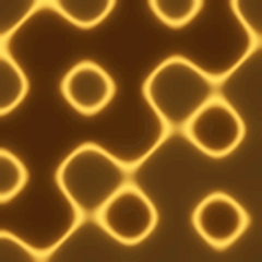
PL. 125 · FIELDS / SURFACE / TRIPLY PERIODIC
Schwarz P Surface
Hermann Amandus Schwarz, 1865 · nodal form: von Schnering & Nesper, 1991
OPEN THE LIVE PLATE ▸DEFINITION
g(x, y, z) = cos x + cos y + cos z
walls where |g| < δ, sliced on z = ω·t
NOTES
H. A. Schwarz worked through Plateau problem after Plateau problem for skew polygonal wire frames in the 1860s, and two of the surfaces that fell out of that work, now called P and D, turned out decades later to be among the simplest triply periodic minimal surfaces there are: each splits space into two congruent labyrinths that never touch, mean curvature zero at every point. Alan Schoen later named this one Primitive, P, because its own symmetry is that of the plain cubic lattice. The plate slices a tilted, drifting plane through the same fixed field the gyroid plate slices — the same instrument aimed at a different equation. Honesty about the formula: the true minimal P surface has no closed form either; cos x + cos y + cos z = 0 is the nodal (trigonometric) approximation crystallographers use in its place, and the wall drawn is its zero set thickened to δ. Bonnet proved in 1853 that a minimal surface bends into a continuous family of others without stretching or tearing, and P, D and the gyroid are three members of one such family, not three unrelated shapes: the Schwarz D surface sits at 0 degrees of that bending, the gyroid at about 38.015 degrees, this plate at 90.
PROVENANCE
- Origin
- H. A. Schwarz, communicated 1865 to the Gesellschaft der Wissenschaften zu Göttingen; collected in Gesammelte Mathematische Abhandlungen, Erster Band, J. Springer, Berlin, 1890 (the chapter "Fortgesetzte Untersuchungen über specielle Minimalflächen")
- Approximation
- H. G. von Schnering & R. Nesper, "Nodal surfaces of Fourier series: fundamental invariants of structured matter", Z. Physik B — Condensed Matter 83, 407–412, 1991 — the same paper gyroid cites for its own nodal form; it gives the leading-Fourier-term nodal surface for P, D, G and I-WP alike, and cos x + cos y + cos z = 0 is its P-surface term. The true Schwarz surface has no such closed form
- Standing
- Nineteenth-century geometry; public domain. Pre-DOI, so nothing about the surface itself is cited that cannot be checked. No patent
- Bonnet family
- O. Bonnet showed in 1853 that a minimal surface bends into a continuous family of others, every member minimal; P, D and the gyroid are three members of one such family, not three unrelated shapes. The angle figures given here — the Schwarz D surface at 0 degrees, the gyroid at about 38.015, P at 90 — are reported in H. Karcher, "The triply periodic minimal surfaces of Alan Schoen and their constant mean curvature companions", Manuscripta Mathematica 64(3), 1989, 291–357, doi:10.1007/BF01165824 (checked against Crossref on title, author, venue and year), and confirmed since; not independently re-derived for this plate
- Constants
- Scale counts surface periods across the frame; δ is wall thickness in field units, where |g| tops out at exactly 3 — twice the gyroid fields measured 1.5, because x, y and z enter as three independent cosines here rather than the gyroid coupled sin·cos cross terms, so thick is ranged twice as wide for the same visual density (measured: mean wall coverage 4–34% across the declared range, essentially independent of scale, drift and tilt)
- Source
- doi:10.1007/BF01313411
TOUCHDESIGNER · GLSL
The same shader this plate runs, reframed for a GLSL TOP. Pasted bare it renders the published constants as a still frame; wire absTime.seconds into u_t on the Vectors page to animate it.
// FORMA — PL. 125 · SCHWARZ P SURFACE — Hermann Amandus Schwarz, 1865 · nodal form: von Schnering & Nesper, 1991
//   g(x, y, z) = cos x + cos y + cos z
//   walls where |g| < δ, sliced on z = ω·t
// TouchDesigner port — paste into a GLSL TOP's pixel shader. Set the
// resolution on the TOP's Common page. As pasted it renders the published
// constants as a still frame; to animate, add a uniform named u_t on the
// GLSL TOP's Vectors 1 page with the expression absTime.seconds.
// Constants are consts — edit to tweak; comments give the measured range.
// Written from the published mathematics, not adapted from any code.

#define u_res (uTDOutputInfo.res.zw)
uniform float u_t;               // absTime.seconds on the Vectors page; unset = still

const float u_phase = 0.0459;    // this plate's own grid phase, 0..1
// FORMA's FIELDS accent as cosine-gradient coefficients
const vec3 u_pal_a = vec3(0.46, 0.3031, 0.11);
const vec3 u_pal_b = vec3(0.5, 0.3294, 0.1196);
const vec3 u_pal_c = vec3(1, 1, 1);
const vec3 u_pal_d = vec3(0, 0.05, 0.1);

const float p_scale = 3.0;         // periods across · live 1.5 .. 6
const float p_thick = 0.5;         // δ — wall thickness · live 0.15 .. 1.2
const float p_drift = 0.25;        // ω — slice drift · live 0.05 .. 0.8
const float p_tilt  = 0.18;        // plane tilt · live 0 .. 0.5

/* The order's ramp — the same cosine formulation the JS kit uses, so a
   plate keeps its classification colour in either language. */
vec3 ramp(float t){
  return clamp(u_pal_a + u_pal_b * cos(6.28318530718 * (u_pal_c * t + u_pal_d)), 0.0, 1.0);
}

/* Sawtooth and triangle on this plate's phase, mirroring the JS kit. */
float cycle(float t, float period){ return fract(t / period + u_phase); }
float pingpong(float t, float period){
  float u = cycle(t, period);
  return u < 0.5 ? u * 2.0 : 2.0 - u * 2.0;
}


vec3 plate(vec2 uv){
  /* The same oblique slice, the same two tints as gyroid — smoothstep here
     mirrors the hermite the JS path already uses, so the wall falls off
     identically on both paths. Only the level set changes: an independent
     cosine per axis, rather than the coupled sin*cos cross terms gyroid
     uses — which is also why |g| here tops out at 3 rather than the 1.5
     the gyroid field reaches. */
  float ar = u_res.y / u_res.x;
  float k = p_scale * 6.28318530718;
  float X = uv.x * k, Y = uv.y * ar * k;
  float Z = u_phase * 6.283 + u_t * p_drift + p_tilt * (X + Y);
  float g = cos(X) + cos(Y) + cos(Z);
  float wall = 1.0 - smoothstep(0.0, p_thick, abs(g));
  vec3 base = (g > 0.0 ? ramp(0.95) : ramp(0.13)) * 0.22;
  return min(base + ramp(0.88) * wall, vec3(1.0));
}

out vec4 fragColor;
void main(){
  // FORMA's uv runs y-down, matching its canvas; TD's vUV runs up
  vec2 uv = vec2(vUV.s, 1.0 - vUV.t);
  fragColor = TDOutputSwizzle(vec4(plate(uv), 1.0));
}
NUKE · BLINKSCRIPT
The same shader this plate runs, transpiled to a BlinkScript kernel. Paste it into a BlinkScript node's Kernel Source and press Recompile; every constant arrives as a knob at its published value, and u_t animates with the expression frame/24. Compiled and rendered in Nuke 17.1, then compared against this plate on the page.
// FORMA — PL. 125 · SCHWARZ P SURFACE — Hermann Amandus Schwarz, 1865 · nodal form: von Schnering & Nesper, 1991
//   g(x, y, z) = cos x + cos y + cos z
//   walls where |g| < δ, sliced on z = ω·t
// Nuke port — a BlinkScript kernel. Paste into a BlinkScript node's Kernel
// Source and press Recompile. Every constant arrives as a knob at its published
// value (the comment gives the measured range); u_t is a knob too — animate it
// with the expression frame/24 or leave it at 0 for the still frame. Written
// from the published mathematics, not adapted from any code.
// Transpiled from the shader this plate runs on the page (GLSL ES 3.00):
// vec → float2/3/4, swizzles expanded, GLSL builtins Blink lacks written out
// as forma_ functions, float literals suffixed. Compiled and rendered in a
// real Nuke (17.1v1) and compared against this plate on the page: 34 of 34.
//
// plate() and its helpers are written to a single exit — the loop that runs
// once. That is not a style: Blink 17.1 drops a conditional early return from
// a called function while Vectorize is on, which is the node default, with no
// warning and no error. Written this way it paints correctly as pasted.

kernel Forma_schwarzp : ImageComputationKernel<ePixelWise>
{
  Image<eWrite> dst;

param:
  float u_t;             // seconds; 0 is the still frame
  float p_scale; // periods across · live 1.5 .. 6
  float p_thick; // δ — wall thickness · live 0.15 .. 1.2
  float p_drift; // ω — slice drift · live 0.05 .. 0.8
  float p_tilt;  // plane tilt · live 0 .. 0.5

local:
  float2 u_res;
  float u_phase;
  float3 u_pal_a, u_pal_b, u_pal_c, u_pal_d;

  void define(){
    defineParam(u_t, "u_t", 0.0f);
    defineParam(p_scale, "p_scale", 3.0f);
    defineParam(p_thick, "p_thick", 0.5f);
    defineParam(p_drift, "p_drift", 0.25f);
    defineParam(p_tilt, "p_tilt", 0.18f);
  }

  void init(){
    u_res = float2(float(dst.bounds.width()), float(dst.bounds.height()));
    u_phase = 0.0459f;    // this plate's own grid phase, 0..1
    // FORMA's FIELDS accent as cosine-gradient coefficients
    u_pal_a = float3(0.46f, 0.3031f, 0.11f);
    u_pal_b = float3(0.5f, 0.3294f, 0.1196f);
    u_pal_c = float3(1.0f, 1.0f, 1.0f);
    u_pal_d = float3(0.0f, 0.05f, 0.1f);
  }

  /* GLSL builtins Blink lacks, written as templates rather than overload sets.
     Blink's operators return expression templates (Swizzle<float,N>), so a call
     passing an expression cannot resolve against an overload set on float2
     against float3 — measured in Nuke 17.1: a float2 expression is ambiguous
     between the two, while scalar-against-vector resolves. A template deduces
     the expression's own type, so the ambiguity cannot arise. */
  template <class T> T forma_fract(T v){ return v - floor(v); }
  template <class T, class S> T forma_mod(T x, S y){ return x - y * floor(x / y); }
  /* Blink's own min/max/clamp take no scalar bound against a vector, which GLSL
     does; v * 0.0f + b is that bound at the vector's own width, and collapses to
     b when v is a scalar, so one template serves both. */
  template <class T, class S> T forma_min(T a, S b){ return min(a, a * 0.0f + b); }
  template <class T, class S> T forma_max(T a, S b){ return max(a, a * 0.0f + b); }
  template <class T, class S> T forma_clamp(T v, S lo, S hi){ return clamp(v, v * 0.0f + lo, v * 0.0f + hi); }
  int forma_min(int a, int b){ return min(a, b); }
  int forma_max(int a, int b){ return max(a, b); }
  /* GLSL step(edge, x) is 1 where x >= edge; floor(sign(x - e) * 0.5 + 1) is
     that exactly, equality included, out of builtins Blink does have. */
  template <class T, class S> T forma_step(S e, T x){ return floor(sign(x - e) * 0.5f + 1.0f); }
  template <class T, class S> T forma_smoothstep(S a, S b, T x){
    T t = forma_clamp((x - a) / (b - a), 0.0f, 1.0f);
    return t * t * (3.0f - 2.0f * t);
  }
  template <class T> float forma_distance(T a, T b){ return length(a - b); }
  float forma_tanh(float x){ float e = exp(2.0f * x); return (e - 1.0f) / (e + 1.0f); }
  float forma_radians(float d){ return d * 0.01745329252f; }
  // the page's hash2 is exact uint32; Blink has int, so the shifts are made
  // logical by masking and the read-back is lifted into 0 .. 2^32
  /* A uint read back as a float. Blink has no unsigned type, so a value past
     2^31 arrives as a negative int and float() of it is negative. Measured on
     gabor, whose own generator then returned uniforms in [-0.5, 0.5) and drew
     a different picture — it compiled, it rendered, and only comparing it with

  /* The order's ramp — the same cosine formulation the JS kit uses, so a
     plate keeps its classification colour in either language. */
  float3 ramp(float t){
    return forma_clamp(u_pal_a + u_pal_b * cos(6.28318530718f * (u_pal_c * t + u_pal_d)), 0.0f, 1.0f);
  }

  /* Sawtooth and triangle on this plate's phase, mirroring the JS kit. */
  float cycle(float t, float period){ return forma_fract(t / period + u_phase); }
  float pingpong(float t, float period){
    float u = cycle(t, period);
    return u < 0.5f ? u * 2.0f : 2.0f - u * 2.0f;
  }


  float3 plate(float2 uv){
    /* The same oblique slice, the same two tints as gyroid — smoothstep here
       mirrors the hermite the JS path already uses, so the wall falls off
       identically on both paths. Only the level set changes: an independent
       cosine per axis, rather than the coupled sin*cos cross terms gyroid
       uses — which is also why |g| here tops out at 3 rather than the 1.5f
       the gyroid field reaches. */
    float ar = u_res.y / u_res.x;
    float k = p_scale * 6.28318530718f;
    float X = uv.x * k;
    float Y = uv.y * ar * k;
    float Z = u_phase * 6.283f + u_t * p_drift + p_tilt * (X + Y);
    float g = cos(X) + cos(Y) + cos(Z);
    float wall = 1.0f - forma_smoothstep(0.0f, p_thick, fabs(g));
    float3 base = (g > 0.0f ? ramp(0.95f) : ramp(0.13f)) * 0.22f;
    return forma_min(base + ramp(0.88f) * wall, float3(1.0f));
  }

  void process(int2 pos){
    // FORMA's uv runs y-down like its canvas; Nuke's rows run up
    float2 uv = float2((float(pos.x) + 0.5f) / u_res.x, 1.0f - (float(pos.y) + 0.5f) / u_res.y);
    float3 c = plate(uv);
    dst() = float4(c.x, c.y, c.z, 1.0f);
  }
};