PL. 137 · FIELDS / PROJECTION / SPHERE TO PLANE
Stereographic Projection
Ptolemy, c. 150 (Hipparchus, 2nd c. BC, attributed) · conformality proved: Edmond Halley, 1695
OPEN THE LIVE PLATE ▸DEFINITION
inverse map, plane → sphere (pole at z = 1):
s = X² + Y²,  (x, y, z) = (2X, 2Y, s−1)/(s+1)
conformal everywhere: circle ↦ circle, angle ↦ same angle
NOTES
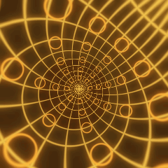
Every point of the sphere but one has a partner on the plane: draw a line from the pole of the sphere through the point, and where that line meets the plane is the answer. The correspondence keeps every angle exactly, which is why a circle traced anywhere on the sphere always lands on the plane as a circle too, never an ellipse — only its size answers to where it sat, ballooning as its true home creeps toward the pole the projection is taken from. This plate reads the correspondence backward: for every point of the frame it asks which point of a graticule-and-circles globe would land there, and paints that answer. The globe turns slowly on a tilted axis while the projection itself holds still, a planisphere in motion, built from the instrument this mathematics was invented for. Stereographic projection is also the map that turns every rotation of the sphere into a Mobius transformation of the plane — the family whose disk-preserving subgroup drives the isometries hyperbolic (PL. 85) builds from z → (z + a)/(1 + ā z), and whose modular subgroup sorts the circles ford (PL. 54) draws into Farey neighbours. Three plates drawing what one group does to circles, on three different stages. hopf (PL. 122) projects a different object through the same construction one dimension up: fibres of the three-sphere, carried down by a stereographic map taken from a point of a three-sphere rather than a two-sphere. This plate stays home and draws the projection itself, the base case the other three all depend on.
PROVENANCE
- Origin
- Ptolemy, Planisphaerium, c. 150 CE — the earliest extant written description of the construction, made for the astrolabe. The attribution to Hipparchus (2nd century BC) comes from the commentator Synesius of Cyrene, writing around 400 CE, three centuries after Hipparchus and independent of any Hipparchus text that survives; some historians (G. J. Toomer, John North, David King) accept it, others consider the evidence absent. Reported here as an attribution rather than a fact
- The name
- Francois dAguilon coined "stereographic" in Opticorum libri sex philosophis juxta ac mathematicis utiles, Antwerp, 1613 — centuries after the construction itself
- Circles to circles
- The theorem behind this is traced to a lemma in Apollonius of Perga, Conics, c. 200 BC — a fact about circles on a cone, not a statement about the projection, and cited here as the classical geometry it is rather than a forced identifier: no DOI exists for a work this old
- Conformality, proved
- Thomas Harriot proved stereographic projection preserves angles in the late 16th century but never published it — the proof sat among his papers for more than three centuries. The first published proof is E. Halley, "An easie demonstration of the analogy of the logarithmick tangents to the meridian line or sum of the secants...", Philosophical Transactions 19, 1696 (the volume spans 1695-97), 202-214, doi:10.1098/rstl.1695.0028 — verified against Crossref on title, author, year and venue. This papers own subject is a Mercator-chart navigation result, the analogy between the logarithmic tangent and the meridian line; the conformality proof is embedded in it as "Lemma II". In Halleys own words, from the historical record: the lemma he had "lately... from Mr. Ab. de Moivre", and he afterward learned "from Dr. Hook that he long ago produced the same thing before the [Royal] society", but "the demonstration and the rest of the discourse is my own." src points at this paper for that lemma, not for a paper about stereographic projection as its main subject — a reader following the link should not expect one
- Standing
- Public domain — classical geometry and a 1695 Royal Society paper. No patent is possible on either
- What the plate adds
- Two patterns painted on one sphere: a graticule (meridians and parallels, the classical reference lines) and forty small circles of one fixed true spherical radius, arranged clear of both poles. The graticule shows the map is legible; the circles show it is conformal — same true size everywhere on the sphere, different apparent size in the plane, and still circles rather than ellipses wherever they land, which is the property this plate is named for
- Constants
- merid and parall set the graticule density (longitude and latitude line counts) and cost nothing extra per pixel — both tests are closed-form nearest-line lookups, not loops over the line count. width is the line half-width for both the graticule and the test circles, in the same spherical-radian units testr uses. testr is the fixed spherical radius of the forty test circles; the lattice they sit on (5 colatitude bands by 8 longitude columns, kept at least 25 degrees off both poles) is a fixed internal structure, not a slider, and the nearest-circle search checks all 40 by brute force rather than assuming a circle stays inside one lattice cell, so testr has no correctness ceiling — only a legibility one, which is why its declared range (0.05 to 0.20 rad, 2.9 to 11.5 degrees) stays comfortably under the roughly 13-degree spacing of the lattice itself. spin is the angular rate of the sphere itself, always positive on its declared range (0.03 minimum) so the plate never stops moving, which is what keeps it an honest drift plate rather than one that happens to sit still at some parameter corner. reach is the half-width of the visible plane in sphere radii — how close to the projection pole the edge of the frame reaches; larger values show more of the size distortion the conformality claim depends on, at the cost of compressing the near hemisphere toward the centre of the frame. The axial tilt itself (0.42 rad, about 24 degrees) is a fixed constant rather than a seventh slider — swept by hand from 0.2 to 0.6, every value reads as a globe turning on a tilted stand rather than a flat disc spinning in place, so there is no shape here for a dial to expose, only a look, and the plate already carries six constants with real mathematical content. PHASE sets both the tilt axis direction and the starting angle of the spin, so no two renders of this plate share a wobble
- Checked, not just plotted
- The rotation undo (spin, then tilt, both inverted from how the sphere would be built up) was verified numerically before this draft was written: over a grid of sample points the recovered rest-frame vector has length 1 to within 4.4e-16, which is floating-point noise rather than an approximation error, confirming the two-step Rodrigues construction is a genuine isometry. Liveness was swept the way regenerate actually jitters — all six constants at once, thirty random tuples, random t and PHASE — against a scratchpad reimplementation of the field, and came back 30/30 live with the tightest case still well clear of the floor
- Source
- doi:10.1098/rstl.1695.0028
TOUCHDESIGNER · GLSL
The same shader this plate runs, reframed for a GLSL TOP. Pasted bare it renders the published constants as a still frame; wire absTime.seconds into u_t on the Vectors page to animate it.
// FORMA — PL. 137 · STEREOGRAPHIC PROJECTION — Ptolemy, c. 150 (Hipparchus, 2nd c. BC, attributed) · conformality proved: Edmond Halley, 1695
//   inverse map, plane → sphere (pole at z = 1):
//   s = X² + Y²,  (x, y, z) = (2X, 2Y, s−1)/(s+1)
//   conformal everywhere: circle ↦ circle, angle ↦ same angle
// TouchDesigner port — paste into a GLSL TOP's pixel shader. Set the
// resolution on the TOP's Common page. As pasted it renders the published
// constants as a still frame; to animate, add a uniform named u_t on the
// GLSL TOP's Vectors 1 page with the expression absTime.seconds.
// Constants are consts — edit to tweak; comments give the measured range.
// Written from the published mathematics, not adapted from any code.

#define u_res (uTDOutputInfo.res.zw)
uniform float u_t;               // absTime.seconds on the Vectors page; unset = still

const float u_phase = 0.1232;    // this plate's own grid phase, 0..1
// FORMA's FIELDS accent as cosine-gradient coefficients
const vec3 u_pal_a = vec3(0.46, 0.3031, 0.11);
const vec3 u_pal_b = vec3(0.5, 0.3294, 0.1196);
const vec3 u_pal_c = vec3(1, 1, 1);
const vec3 u_pal_d = vec3(0, 0.05, 0.1);

const float p_merid  = 24.0;        // meridians — longitude count · live 8 .. 36
const float p_parall = 12.0;        // parallels — latitude count · live 4 .. 18
const float p_width  = 0.02;        // line width (spherical rad) · live 0.01 .. 0.045
const float p_testr  = 0.11;        // test-circle spherical radius · live 0.05 .. 0.2
const float p_spin   = 0.15;        // ω — spin rate · live 0.03 .. 0.4
const float p_reach  = 2.6;         // R — view reach (sphere radii) · live 1.6 .. 4

/* The order's ramp — the same cosine formulation the JS kit uses, so a
   plate keeps its classification colour in either language. */
vec3 ramp(float t){
  return clamp(u_pal_a + u_pal_b * cos(6.28318530718 * (u_pal_c * t + u_pal_d)), 0.0, 1.0);
}

/* Sawtooth and triangle on this plate's phase, mirroring the JS kit. */
float cycle(float t, float period){ return fract(t / period + u_phase); }
float pingpong(float t, float period){
  float u = cycle(t, period);
  return u < 0.5 ? u * 2.0 : 2.0 - u * 2.0;
}


vec3 plate(vec2 uv){
  float TAU = 6.283185307179586;
  float merid = floor(p_merid + 0.5);
  float parall = floor(p_parall + 0.5);
  float width = p_width, testr = p_testr;

  /* Same fixed obliquity as the JS path -- see the draft header. */
  float TILT = 0.42;
  float axAz = u_phase * TAU;
  float nx = cos(axAz), ny = sin(axAz);
  float psi = u_phase * TAU + u_t * p_spin;
  float cosT = cos(TILT), sinT = sin(TILT);
  float cosPsi = cos(psi), sinPsi = sin(psi);

  float ar = u_res.y / u_res.x, fit = min(1.0, ar);
  float R = p_reach;
  float X = (uv.x - 0.5) * 2.0 * R / fit;
  float Y = (uv.y - 0.5) * 2.0 * R * ar / fit;
  float s = X * X + Y * Y, inv = 1.0 / (s + 1.0);
  float p0x = 2.0 * X * inv, p0y = 2.0 * Y * inv, p0z = (s - 1.0) * inv;

  /* Undo the rotation -- Rodrigues, exact, tilt then spin, both inverted.
     No cross-fragment cache exists on the GPU, so this and the 40-circle
     search below both run fresh per pixel; the whole body still measures
     far under budget on every gl plate in this atlas. */
  float dotN = nx * p0x + ny * p0y;
  float crx = ny * p0z, cry = -nx * p0z, crz = nx * p0y - ny * p0x;
  float p1x = p0x * cosT - crx * sinT + nx * dotN * (1.0 - cosT);
  float p1y = p0y * cosT - cry * sinT + ny * dotN * (1.0 - cosT);
  float p1z = p0z * cosT - crz * sinT;

  float rx = p1x * cosPsi + p1y * sinPsi;
  float ry = -p1x * sinPsi + p1y * cosPsi;
  float rz = p1z;

  float theta = acos(clamp(rz, -1.0, 1.0));
  float phi = atan(ry, rx);
  if (phi < 0.0) phi += TAU;

  float dPhi = TAU / merid;
  float phi0 = mod(floor(phi / dPhi + 0.5), merid) * dPhi;
  float distMerid = abs(asin(clamp(rx * sin(phi0) - ry * cos(phi0), -1.0, 1.0)));

  float PI = 3.141592653589793;
  float dTheta = PI / parall;
  float kPar = clamp(floor(theta / dTheta + 0.5), 1.0, parall - 1.0);
  float distPar = abs(theta - kPar * dTheta);

  float gW = max(1.0 - smoothstep(0.0, width, distMerid),
                 1.0 - smoothstep(0.0, width, distPar));

  /* The same fixed 5x8 lattice as the JS path, rebuilt inline -- 40 is a
     literal loop bound, never slider-driven. */
  float bandLo = 0.436, bandHi = PI - 0.436;
  float best = -2.0;
  for (int j = 0; j < 5; j++){
    float thJ = bandLo + (float(j) + 0.5) * (bandHi - bandLo) / 5.0;
    float sr = sin(thJ), cz = cos(thJ);
    for (int i = 0; i < 8; i++){
      float ph = (float(i) + 0.5) * TAU / 8.0;
      float d = rx * (sr * cos(ph)) + ry * (sr * sin(ph)) + rz * cz;
      best = max(best, d);
    }
  }
  float ringDist = abs(acos(clamp(best, -1.0, 1.0)) - testr);
  float rW = 1.0 - smoothstep(0.0, width, ringDist);

  vec3 base = (rz > 0.0 ? ramp(0.95) : ramp(0.14)) * 0.16;
  vec3 col = base;
  col += (ramp(0.88) - col) * gW;
  col += (ramp(0.06) - col) * rW;
  return col;
}

out vec4 fragColor;
void main(){
  // FORMA's uv runs y-down, matching its canvas; TD's vUV runs up
  vec2 uv = vec2(vUV.s, 1.0 - vUV.t);
  fragColor = TDOutputSwizzle(vec4(plate(uv), 1.0));
}
NUKE · BLINKSCRIPT
The same shader this plate runs, transpiled to a BlinkScript kernel. Paste it into a BlinkScript node's Kernel Source and press Recompile; every constant arrives as a knob at its published value, and u_t animates with the expression frame/24. Compiled and rendered in Nuke 17.1, then compared against this plate on the page.
// FORMA — PL. 137 · STEREOGRAPHIC PROJECTION — Ptolemy, c. 150 (Hipparchus, 2nd c. BC, attributed) · conformality proved: Edmond Halley, 1695
//   inverse map, plane → sphere (pole at z = 1):
//   s = X² + Y²,  (x, y, z) = (2X, 2Y, s−1)/(s+1)
//   conformal everywhere: circle ↦ circle, angle ↦ same angle
// Nuke port — a BlinkScript kernel. Paste into a BlinkScript node's Kernel
// Source and press Recompile. Every constant arrives as a knob at its published
// value (the comment gives the measured range); u_t is a knob too — animate it
// with the expression frame/24 or leave it at 0 for the still frame. Written
// from the published mathematics, not adapted from any code.
// Transpiled from the shader this plate runs on the page (GLSL ES 3.00):
// vec → float2/3/4, swizzles expanded, GLSL builtins Blink lacks written out
// as forma_ functions, float literals suffixed. Compiled and rendered in a
// real Nuke (17.1v1) and compared against this plate on the page: 34 of 34.
//
// plate() and its helpers are written to a single exit — the loop that runs
// once. That is not a style: Blink 17.1 drops a conditional early return from
// a called function while Vectorize is on, which is the node default, with no
// warning and no error. Written this way it paints correctly as pasted.

kernel Forma_stereographic : ImageComputationKernel<ePixelWise>
{
  Image<eWrite> dst;

param:
  float u_t;             // seconds; 0 is the still frame
  float p_merid;  // meridians — longitude count · live 8 .. 36
  float p_parall; // parallels — latitude count · live 4 .. 18
  float p_width;  // line width (spherical rad) · live 0.01 .. 0.045
  float p_testr;  // test-circle spherical radius · live 0.05 .. 0.2
  float p_spin;   // ω — spin rate · live 0.03 .. 0.4
  float p_reach;  // R — view reach (sphere radii) · live 1.6 .. 4

local:
  float2 u_res;
  float u_phase;
  float3 u_pal_a, u_pal_b, u_pal_c, u_pal_d;

  void define(){
    defineParam(u_t, "u_t", 0.0f);
    defineParam(p_merid, "p_merid", 24.0f);
    defineParam(p_parall, "p_parall", 12.0f);
    defineParam(p_width, "p_width", 0.02f);
    defineParam(p_testr, "p_testr", 0.11f);
    defineParam(p_spin, "p_spin", 0.15f);
    defineParam(p_reach, "p_reach", 2.6f);
  }

  void init(){
    u_res = float2(float(dst.bounds.width()), float(dst.bounds.height()));
    u_phase = 0.1232f;    // this plate's own grid phase, 0..1
    // FORMA's FIELDS accent as cosine-gradient coefficients
    u_pal_a = float3(0.46f, 0.3031f, 0.11f);
    u_pal_b = float3(0.5f, 0.3294f, 0.1196f);
    u_pal_c = float3(1.0f, 1.0f, 1.0f);
    u_pal_d = float3(0.0f, 0.05f, 0.1f);
  }

  /* GLSL builtins Blink lacks, written as templates rather than overload sets.
     Blink's operators return expression templates (Swizzle<float,N>), so a call
     passing an expression cannot resolve against an overload set on float2
     against float3 — measured in Nuke 17.1: a float2 expression is ambiguous
     between the two, while scalar-against-vector resolves. A template deduces
     the expression's own type, so the ambiguity cannot arise. */
  template <class T> T forma_fract(T v){ return v - floor(v); }
  template <class T, class S> T forma_mod(T x, S y){ return x - y * floor(x / y); }
  /* Blink's own min/max/clamp take no scalar bound against a vector, which GLSL
     does; v * 0.0f + b is that bound at the vector's own width, and collapses to
     b when v is a scalar, so one template serves both. */
  template <class T, class S> T forma_min(T a, S b){ return min(a, a * 0.0f + b); }
  template <class T, class S> T forma_max(T a, S b){ return max(a, a * 0.0f + b); }
  template <class T, class S> T forma_clamp(T v, S lo, S hi){ return clamp(v, v * 0.0f + lo, v * 0.0f + hi); }
  int forma_min(int a, int b){ return min(a, b); }
  int forma_max(int a, int b){ return max(a, b); }
  /* GLSL step(edge, x) is 1 where x >= edge; floor(sign(x - e) * 0.5 + 1) is
     that exactly, equality included, out of builtins Blink does have. */
  template <class T, class S> T forma_step(S e, T x){ return floor(sign(x - e) * 0.5f + 1.0f); }
  template <class T, class S> T forma_smoothstep(S a, S b, T x){
    T t = forma_clamp((x - a) / (b - a), 0.0f, 1.0f);
    return t * t * (3.0f - 2.0f * t);
  }
  template <class T> float forma_distance(T a, T b){ return length(a - b); }
  float forma_tanh(float x){ float e = exp(2.0f * x); return (e - 1.0f) / (e + 1.0f); }
  float forma_radians(float d){ return d * 0.01745329252f; }
  // the page's hash2 is exact uint32; Blink has int, so the shifts are made
  // logical by masking and the read-back is lifted into 0 .. 2^32
  /* A uint read back as a float. Blink has no unsigned type, so a value past
     2^31 arrives as a negative int and float() of it is negative. Measured on
     gabor, whose own generator then returned uniforms in [-0.5, 0.5) and drew
     a different picture — it compiled, it rendered, and only comparing it with

  /* The order's ramp — the same cosine formulation the JS kit uses, so a
     plate keeps its classification colour in either language. */
  float3 ramp(float t){
    return forma_clamp(u_pal_a + u_pal_b * cos(6.28318530718f * (u_pal_c * t + u_pal_d)), 0.0f, 1.0f);
  }

  /* Sawtooth and triangle on this plate's phase, mirroring the JS kit. */
  float cycle(float t, float period){ return forma_fract(t / period + u_phase); }
  float pingpong(float t, float period){
    float u = cycle(t, period);
    return u < 0.5f ? u * 2.0f : 2.0f - u * 2.0f;
  }


  float3 plate(float2 uv){
    float TAU = 6.283185307179586f;
    float merid = floor(p_merid + 0.5f);
    float parall = floor(p_parall + 0.5f);
    float width = p_width;
    float testr = p_testr;

    /* Same fixed obliquity as the JS path -- see the draft header. */
    float TILT = 0.42f;
    float axAz = u_phase * TAU;
    float nx = cos(axAz);
    float ny = sin(axAz);
    float psi = u_phase * TAU + u_t * p_spin;
    float cosT = cos(TILT);
    float sinT = sin(TILT);
    float cosPsi = cos(psi);
    float sinPsi = sin(psi);

    float ar = u_res.y / u_res.x;
    float fit = forma_min(1.0f, ar);
    float R = p_reach;
    float X = (uv.x - 0.5f) * 2.0f * R / fit;
    float Y = (uv.y - 0.5f) * 2.0f * R * ar / fit;
    float s = X * X + Y * Y;
    float inv = 1.0f / (s + 1.0f);
    float p0x = 2.0f * X * inv;
    float p0y = 2.0f * Y * inv;
    float p0z = (s - 1.0f) * inv;

    /* Undo the rotation -- Rodrigues, exact, tilt then spin, both inverted.
       No cross-fragment cache exists on the GPU, so this and the 40-circle
       search below both run fresh per pixel; the whole body still measures
       far under budget on every gl plate in this atlas. */
    float dotN = nx * p0x + ny * p0y;
    float crx = ny * p0z;
    float cry = -nx * p0z;
    float crz = nx * p0y - ny * p0x;
    float p1x = p0x * cosT - crx * sinT + nx * dotN * (1.0f - cosT);
    float p1y = p0y * cosT - cry * sinT + ny * dotN * (1.0f - cosT);
    float p1z = p0z * cosT - crz * sinT;

    float rx = p1x * cosPsi + p1y * sinPsi;
    float ry = -p1x * sinPsi + p1y * cosPsi;
    float rz = p1z;

    float theta = acos(forma_clamp(rz, -1.0f, 1.0f));
    float phi = atan2(ry, rx);
    if (phi < 0.0f) phi += TAU;

    float dPhi = TAU / merid;
    float phi0 = forma_mod(floor(phi / dPhi + 0.5f), merid) * dPhi;
    float distMerid = fabs(asin(forma_clamp(rx * sin(phi0) - ry * cos(phi0), -1.0f, 1.0f)));

    float forma_PI = 3.141592653589793f;
    float dTheta = forma_PI / parall;
    float kPar = forma_clamp(floor(theta / dTheta + 0.5f), 1.0f, parall - 1.0f);
    float distPar = fabs(theta - kPar * dTheta);

    float gW = forma_max(1.0f - forma_smoothstep(0.0f, width, distMerid),
                   1.0f - forma_smoothstep(0.0f, width, distPar));

    /* The same fixed 5x8 lattice as the JS path, rebuilt inline -- 40 is a
       literal loop bound, never slider-driven. */
    float bandLo = 0.436f;
    float bandHi = forma_PI - 0.436f;
    float best = -2.0f;
    for (int j = 0; j < 5; j++){
      float thJ = bandLo + (float(j) + 0.5f) * (bandHi - bandLo) / 5.0f;
      float sr = sin(thJ);
      float cz = cos(thJ);
      for (int i = 0; i < 8; i++){
        float ph = (float(i) + 0.5f) * TAU / 8.0f;
        float d = rx * (sr * cos(ph)) + ry * (sr * sin(ph)) + rz * cz;
        best = forma_max(best, d);
      }
    }
    float ringDist = fabs(acos(forma_clamp(best, -1.0f, 1.0f)) - testr);
    float rW = 1.0f - forma_smoothstep(0.0f, width, ringDist);

    float3 base = (rz > 0.0f ? ramp(0.95f) : ramp(0.14f)) * 0.16f;
    float3 col = base;
    col += (ramp(0.88f) - col) * gW;
    col += (ramp(0.06f) - col) * rW;
    return col;
  }

  void process(int2 pos){
    // FORMA's uv runs y-down like its canvas; Nuke's rows run up
    float2 uv = float2((float(pos.x) + 0.5f) / u_res.x, 1.0f - (float(pos.y) + 0.5f) / u_res.y);
    float3 c = plate(uv);
    dst() = float4(c.x, c.y, c.z, 1.0f);
  }
};